
In the previous article, AI-Native Game Dev in Practice · From Asset Reuse to Experience Reuse, I made one argument: during the gameplay-validation phase there is no need to wait for finished art — one can reuse existing assets and recompose them with AI, bringing the gameplay up first in order to validate it. That article left an open thread — a promise to take a concrete case and run this pipeline end to end.
This article is that concrete case.
The example chosen is reverse-engineering the character and monster assets — mesh, skeleton, animation, material — of a certain third-person shooter out of the game’s package files, running them through a self-built pipeline into the target engine, and converting them into usable assets that can be bound to a skeleton, animate, and carry a material. The process encountered more than a dozen pitfalls: from “the import collapses the entire model into a single blob,” to “what appears to be five LOD levels is in fact false,” to “the material, once assigned, renders as a blotchy surface.”
This is not an article about “how to move assets around.” It is a faithful record of reverse-engineering → encountering pitfalls → locating the cause → resolving it, in which every pitfall is accompanied by data evidence rather than vague “watch out for XX” advice. The principal point I wish to establish is this: when confronting an undocumented black box consisting of nothing but binary data, what does one rely upon to disassemble it piece by piece.
Beyond that, what this article truly seeks to validate is not “whether the assets can be imported into the engine” — that is merely the surface. What it validates is this: whether AI can help transform a black-box asset pipeline into an understandable, maintainable, reusable engineering process. Taking something another party packaged, encrypted, and left undocumented, and — with AI’s assistance — prying it open, reading it, supplying the tool’s missing capabilities, and finally distilling it into a pipeline under one’s own control: that is why this piece belongs in the “AI-native development in practice” series. Asset reverse-engineering is merely the vehicle; AI-assisted analysis of a black-box system is the theme.
Positioning and compliance note · This article is a record of learning the engine art pipeline and validating a prototype. Its purpose is to connect the technical chain “from binary asset to usable engine asset,” for research and prototyping. The unpacking employs a community open-source unpacker hosted on GitHub; the work described herein consists of custom extension on top of its source (adding multiple UV sets, correcting scale, correcting orientation, splitting LODs by level, dumping shaders, and so on), and does not involve circumventing the game’s own encryption or protection mechanisms. Throughout, placeholders such as “a certain third-person shooter” and “the target engine” are used; no specific title is named, no package paths are published, and no use of third-party assets in a shipping product is encouraged. This is consistent with the previous article’s premise: external assets serve only as development-phase placeholders for validation, and once validation passes they are replaced by self-made assets.
1. First, establish a clear picture of the pipeline
Before examining each pitfall, let us lay out the whole pipeline. Every pitfall discussed below occurs at one link in this diagram.

Stated concisely, in actual execution order:
“`
Game package → unpack, extract mesh / skeleton / animation / material references
→ Mesh: export FBX (multiple UV sets / correct orientation / correct scale) → import to engine → associate skeleton and animation
→ LOD: export per level, mount per level, tell real from fake levels
→ Material: dump the real GPU shader, reverse out the composition algorithm → engine master material + instances → assign to mesh
→ Validation: per-level data comparison → overwrite the production project → version-control submit
“`
The ordering “mesh → LOD → material” is not arbitrary — it reflects the physical order in which an asset takes shape within the engine: first import the model and animation and orient them correctly, then mount the multi-level LODs properly, and only then assign the material onto this already-oriented, already-leveled mesh. Each link conceals a pitfall that surfaces only through actual execution. The following sections address them in this order, link by link.
2. Unpacking: first determine what can and cannot be obtained
The first step of reverse engineering is to open the game package and inspect its contents.
The tool for this step is a community open-source unpacker hosted on GitHub — the package format was reverse-engineered by the community long ago, and the tool is readily available. The work undertaken here was not cracking from scratch but custom extension on top of its source: the multiple-UV-set export, scale correction, orientation correction, per-level LOD, and GPU-shader dumping discussed below are all features added to this open-source tool.
One point should be made clear at the outset: the substantive effort does not lie in the unpacking. Unpacking is the readily available step the community already solved; what actually demands effort is using AI to help analyze the binary structure, read the GPU shader, and supply the capabilities this open-source tool lacked — converting “can export” into “usable for validation.” This closes the loop with the previous article, From Asset Reuse to Experience Reuse: that article advocated reusing existing assets to validate gameplay, and this one answers the follow-up question of how those external assets actually become usable — the answer being successive rounds of AI-assisted tool-completion and data-checking, not mere relocation.
A realization more important than “extracting the files” is this: what can be obtained and what one assumes can be obtained are frequently not the same thing.
What can be obtained directly after unpacking: the mesh’s vertices and topology, the skeleton hierarchy, skinning weights, animation curves, and the material’s reference relationships to a set of textures (which material uses which images).
What cannot be obtained — or is “obtained but not directly usable”:
- The vertices’ multiple UV sets; by default only the first set is exported. Yet a material’s different textures use precisely different UV sets.
- The multi-level LOD structure is readily misinterpreted by the tool — it appears split into levels, but the split is incorrect (covered in detail below).
- There is no unwrapped albedo texture in the conventional sense. This game’s mechanical-unit materials are procedurally composed — the “textures” extracted are a collection of mask images, lookup tables, and index images; they are not colors intended for human viewing but data from which the shader computes. Applied directly, they produce blotches (detailed in the material section).
Unpacking is therefore not the finish line; it merely opens a crack in the black box. The substantive work lies in the three links that follow: how to orient the mesh, how to distinguish real LODs from false ones, and how to compute the material.
3. Mesh import: three obstacles in succession
Importing the mesh into the engine appears to be the simplest step, yet it presented three obstacles in succession — none of which could be identified by “reading the code,” only by “comparing the data.”
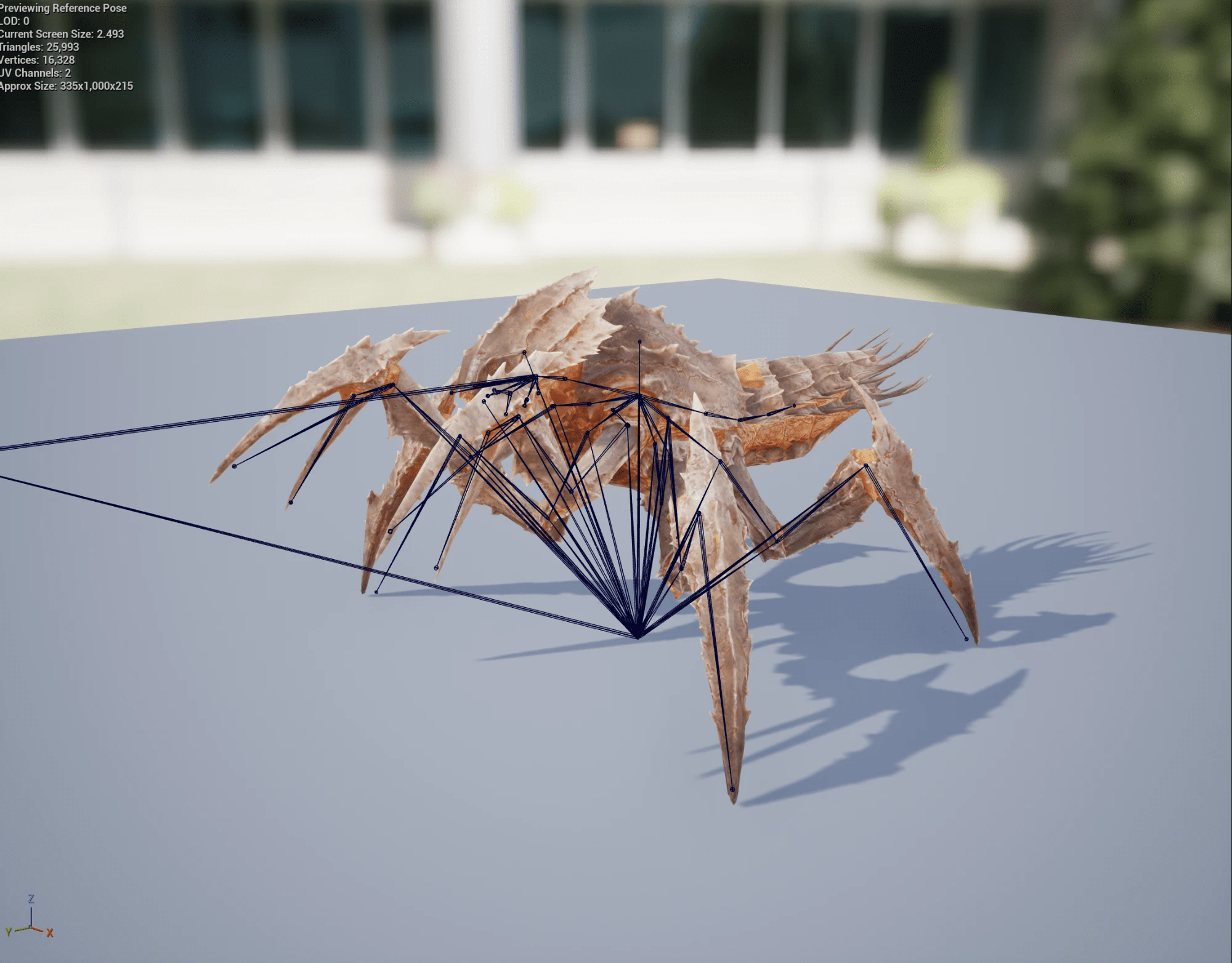
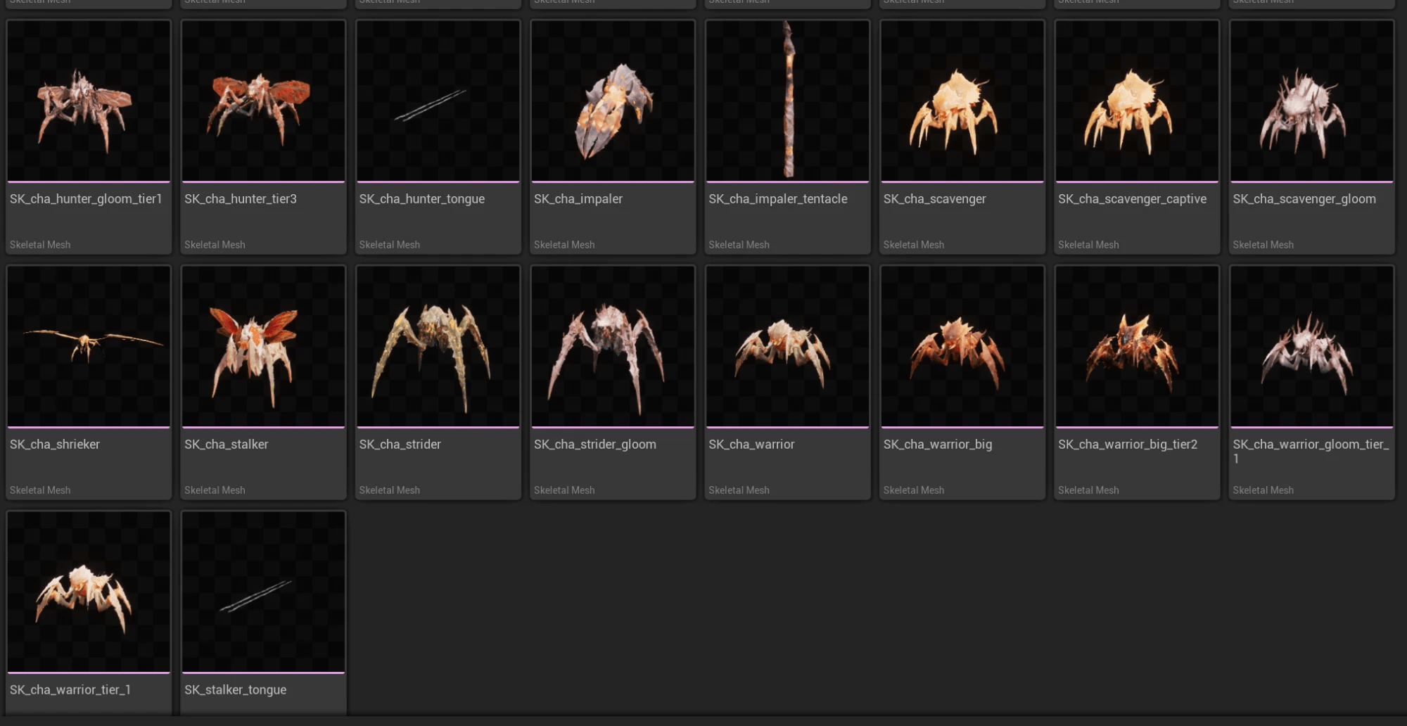
The following subsections walk through the diagnosis of the three obstacles one by one; the “after it works” image above is the result of all three being cleared.
Obstacle 1: import collapses the model into a blob
Symptom: Certain units, after import, collapse entirely toward the origin, with bounding-box height reduced from one meter to one centimeter; other units are entirely unaffected. The same toolset and the same workflow yield two different outcomes.
The investigation proceeded in the manner of detective work:
- First hypothesis: the export tool corrupted the data. A byte comparison of the FBX of a good version against a broken version showed the vertex coordinates were identical — hypothesis ruled out.
- Bone count and skin-cluster count were then compared item by item — all identical, the animation data untouched.
- Finally, the translation column of the bind matrix was compared: the good version’s translation was multiplied by one hundred (converted to centimeters), whereas the broken version’s was not (still expressed in meters).
The true cause emerged: on export, the vertex coordinates were converted from meters to centimeters (×100), but the bone bind matrix’s translation was omitted from the same multiplication. The mesh was thus at centimeter scale while the skeleton’s bind remained at meter scale — a hundred-fold mismatch — and the mesh, driven by a skeleton a hundred times smaller, collapsed.
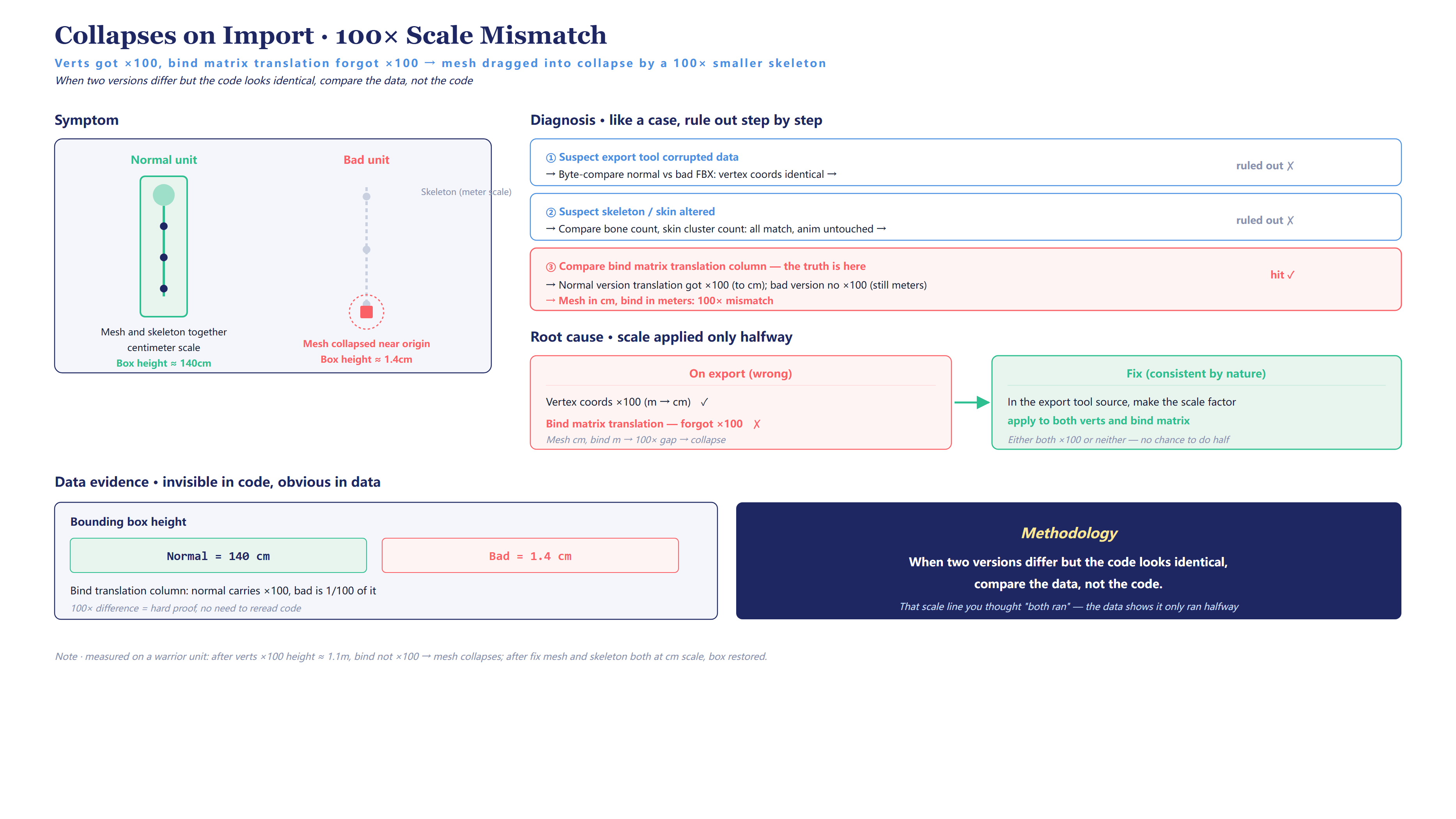
Fix: In the export tool’s source, apply the scale factor to both the vertices and the bind matrix — either both are multiplied or neither is, ensuring inherent consistency and leaving no opportunity for “only half being changed.”
What this obstacle teaches is not “remember to multiply by one hundred,” but a debugging method:
When two versions produce different results yet the code appears identical, compare the data rather than the code. Bounding-box height 140 versus 1.4, the translation column multiplied by one hundred or not — the difference in the data constitutes hard evidence; the line of scaling code one assumed “both paths reach” — the data will reveal that it in fact reached only one path.
Obstacle 2: orientation reversed
Symptom: After import, the character faces away from the camera.
On orientation, five rounds of conjecture all proved wrong:
- Suspected the export tool altered the root-node rotation → compared the FBX root node, bytes identical, ruled out.
- Suspected a missing import option (axis conversion) → added it, still reversed.
- Suspected a discrepancy between “merged export” and “individual export” → files identical, ruled out.
Only at the fifth attempt did the approach change: rather than seeking to understand “why it is reversed,” the bounding-box data was simply aligned. The good version’s bounding-box origin X is +22, the broken version’s is −22 — precisely a one-hundred-eighty-degree rotation about the vertical axis.
Fix: Apply a yaw = 180 rotation on import to cancel the offset, aligning the bounding-box data with the good version. Rotate the whole only; leave vertices and skinning untouched, so the animation remains intact.
Five rounds of conjecture on orientation all proved wrong, then alignment of the bounding-box data resolved it in a single step. At times one need not understand the root cause; it suffices for the data to align. “Understanding why” has value, but when it stubbornly refuses to yield an answer, “aligning with the data” frequently reaches the finish line sooner.
Obstacle 3: UV mismatch causes the material to smear into a blur
Symptom: This obstacle does not surface until the material is assigned — once applied, the material renders as a uniform flesh-colored sheet, lacking the detail texture it should exhibit. The root cause, however, lies in the mesh-import stage, and is therefore covered here.
The material algorithm was correct and the images were correct, so the problem could only reside in the UVs. The initial assumption was that the body material should use the “most regular-looking” UV set (range 0 to 1) — and the result was a blur.
Only by cross-referencing the game shader did the explanation become clear: the main images (index image, normal image) use tiled UVs — range 0 to 8, repeating a low-resolution image eight times over to accumulate detail; that regular 0–1 UV set is intended for the detail-overlay layer, not for the main images.
“Sample the smoothest UV set” does not equate to correctness. A low-resolution index image relies on tiled repetition to accumulate detail; tiled UVs are what it should use. Intuition favors the UV set that “appears clean,” but which set the material algorithm uses must be read from the shader.
Fix: Add multiple-UV-set support to the export tool (export all UV sets), and specify the correct one in the material. This is also why the unpacking section noted that “only the first UV set is exported by default” is a latent hazard — it does not manifest until the material stage.
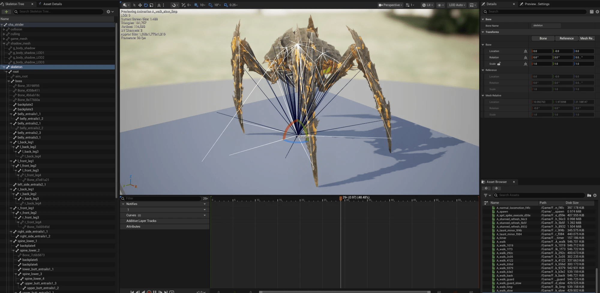
Once the three obstacles are cleared, the mesh is not merely “imported” — the skeleton hierarchy is complete, skinning is correct, and animations are imported as a full set and playable:
4. The LOD trap: apparently five levels, in fact false
Once the mesh is oriented, the next step is handling multi-level LODs. This is the most instructive section of the entire article, and the one that illustrates “data-driven” most thoroughly.
Symptom: After bulk import, certain units’ triangle counts barely decrease as LODs switch — from the highest model down to the lowest, only a twenty-percent reduction, whereas a proper LOD should reduce by more than ninety percent.
The crux is that the unit’s “number of LOD levels” is correct — five levels, not one short. Examining only this surface metric, one would never detect the problem.
How it was discovered: reading the real vertex count per level
The means of catching the problem is not to examine “how many levels,” but to read out the real vertex count of each LOD level, arranged in a row:

Normal unit:
“`
44270 → 15370 → 4548 → 1520 each level roughly halves — a real LOD
“`
Abnormal unit:
“`
111329 → 96698 → 89883 → 88166 only drops 20% — a fake LOD
“`
Placing the two rows of numbers side by side makes real versus false instantly apparent. The normal row is a steep descending staircase; the abnormal one is nearly flat.
True cause: The highest-model mesh of these abnormal units was split into multiple material blocks by UDIM (each block having a similar vertex count). The import tool mistook these UDIM blocks for multiple LOD levels, while the genuinely simplified LODs were ignored. On the surface this amounted to “five levels,” but in reality it was five material blocks of roughly equal size.
Fix: export each LOD level as a separate file
The fix did not entail building complex LOD-recognition logic into the import tool (which would only couple UDIM splitting and LOD detection ever more tightly), but adopted a clean-cut approach:
Export each LOD level as a separate FBX file, then mount them precisely level by level via the engine’s LOD import interface — thereby avoiding the coupling of UDIM splitting and LOD detection entirely. L0 as one file, L1 as one file, L2 as one file, each exported independently, with the engine mounting them one level at a time, affording it no opportunity to “infer which is the LOD on its own.”
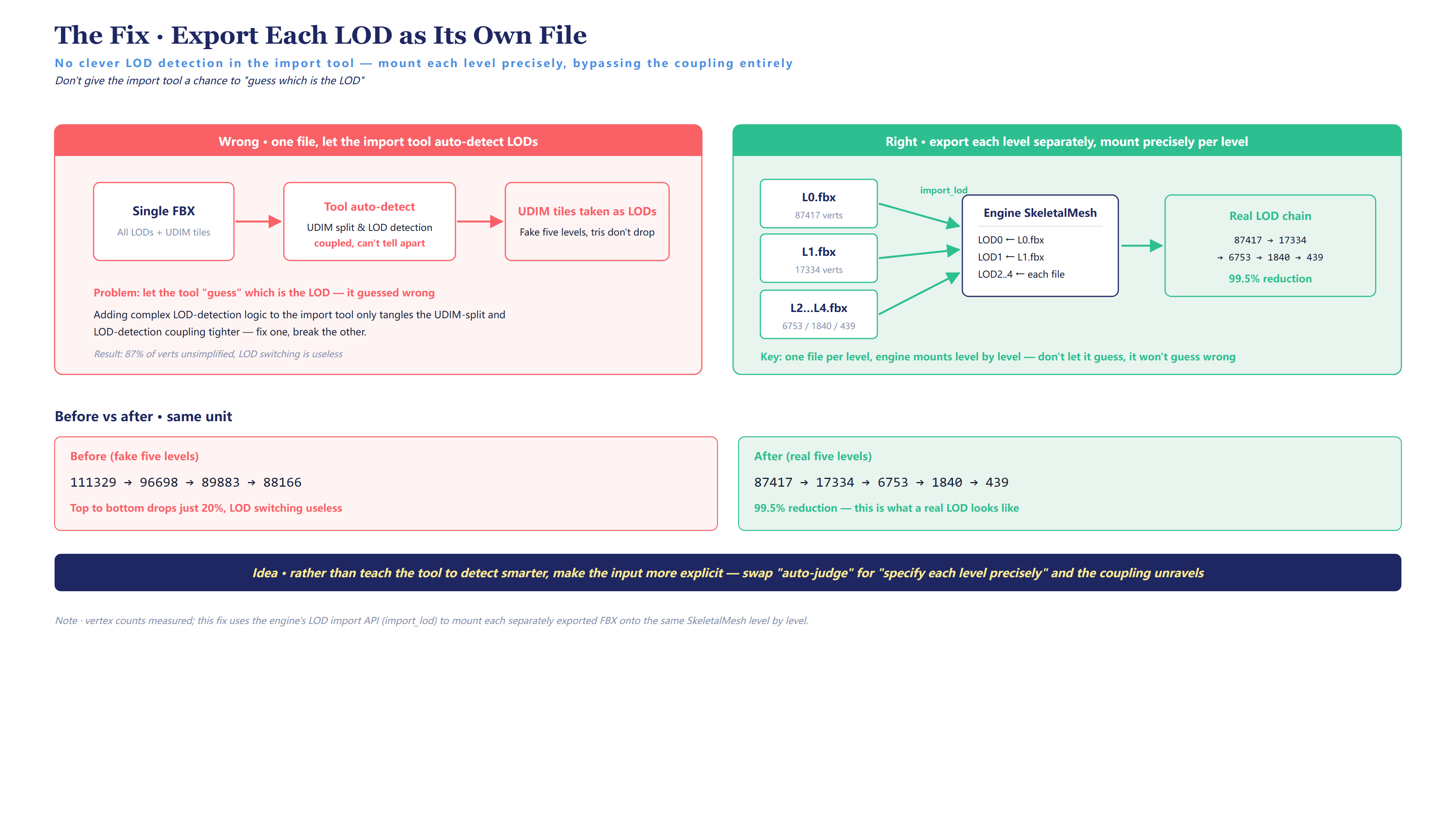
After the fix, the per-level vertex count for the same unit:
“`
87417 → 17334 → 6753 → 1840 → 439 99.5% triangle reduction
“`
This is what a real LOD should look like.
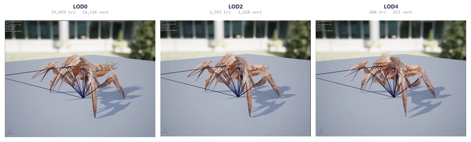
The single most important methodological point in this entire article: per-level data comparison outperforms inspection of surface metrics. The metric “has five LOD levels” is correct, but a comparison of the per-level vertex counts reveals the discrepancy. What catches the problem is never a more sophisticated analysis, but finer data.
5. Material reverse-engineering: not conjectured, but read out of the shader
The mesh is oriented, the LODs are split correctly, and the final step is assigning the material. This is the most technically demanding section of the article.
Mechanical units’ materials have no ready-made color textures, so where does their color actually originate? The initial approach was to examine the texture mapping the unpacker provides, judge by “this one resembles albedo, that one resembles normal,” and apply a ready-made standard master material on top.
This approach failed three times.
- The first time, the index image was applied as albedo — the result was a uniform color block, because the index image is not itself color but a set of index values to be looked up in a palette.
- The second time, the damage image was applied as a normal map — the result was that the metal’s specular was amplified into blotches.
- The third time, an alpha-clip material was treated as “wholly emissive” — and the entire part glowed.
All three failed on the same action: inferring a texture’s purpose from its appearance and filename.
The key turning point: why the shader must be read
After three failed conjectures, the real turning point was not “finding a more accurate basis for conjecture,” but abandoning conjecture entirely — and reading the GPU shader the game actually executes at runtime. With AI’s assistance to decompile it into readable code, exactly how the game computes this color is laid out line by line.
This step is the methodological core of the entire piece, and warrants plain statement: the truth of a material lies not in the texture’s appearance but in the code that computes it. A texture’s appearance will mislead — an index map resembles noise, a damage map resembles a normal; but the shader does not mislead, it states precisely how each image is treated and how it enters the computation. Do not conjecture; examine the evidence — and here the evidence is the shader itself. Those three rounds of speckling were, in essence, the cost of “treating appearance as evidence.”
Reading the shader does admit shortcuts: a material produces many variants, so select the cleanest render stage to read — the one with no lighting, no post-processing, outputting only the material itself; a few hundred lines suffice to read the whole algorithm. Those mixing in lighting and color grading are longer and harder to read. But these are techniques; the core remains that single line: the algorithm is read out, not conjectured.
Once read through, the algorithmic skeleton of the mechanical-unit material is as follows:
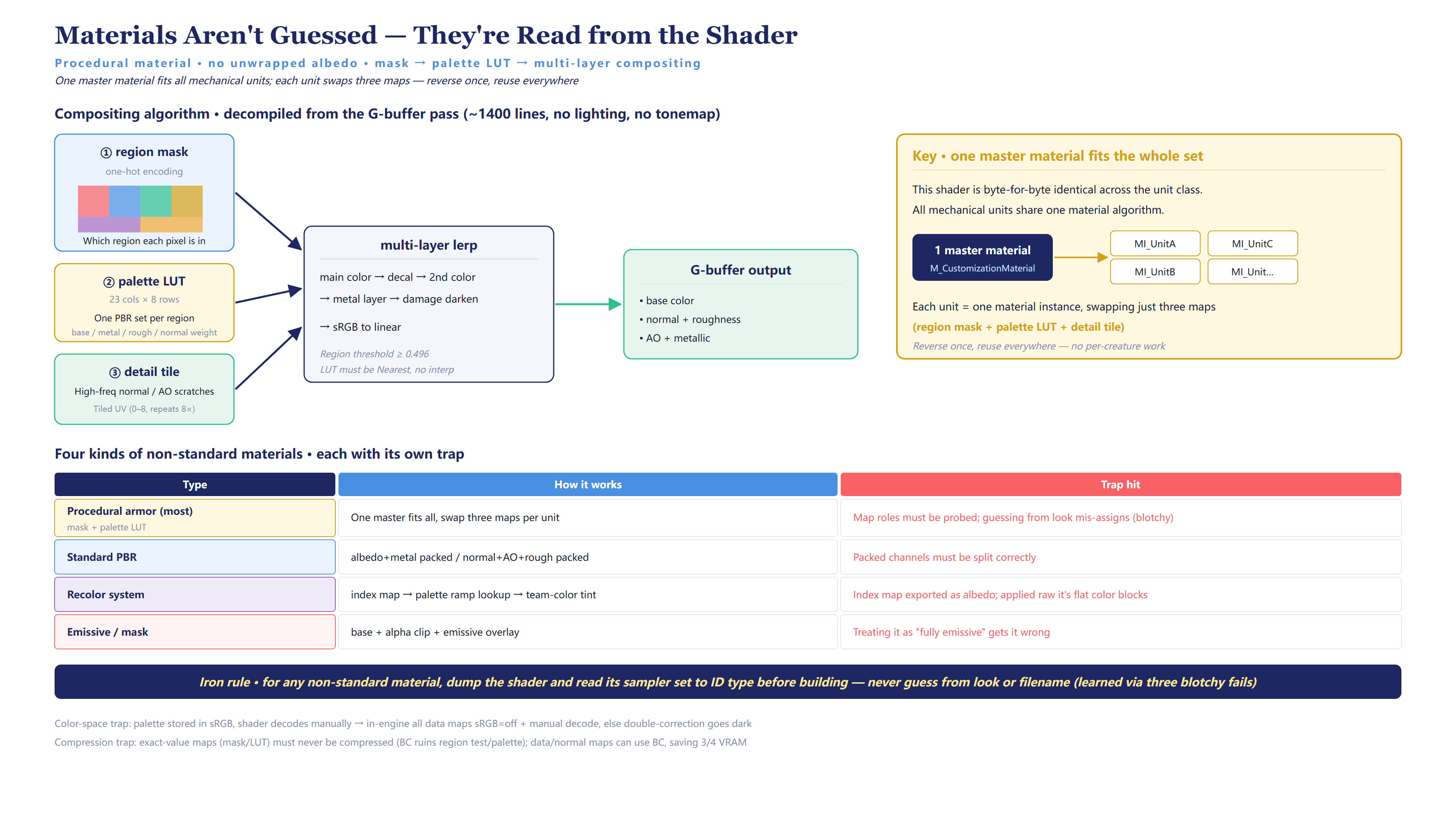
“`
mask image (one-hot encoded, determines which region the current pixel belongs to)
→ palette lookup table (each region looks up a set of PBR properties: base color / metallic / roughness / normal weight…)
→ multi-layer lerp composition (main color → decal → secondary color → metal layer → damage darkening)
→ sRGB to linear
“`
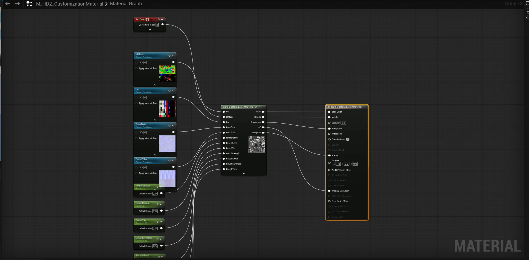
The most elegant aspect: this shader, for the same class of unit (whether infantry or another mechanical type), is byte-for-byte identical. All mechanical units share the same material algorithm, and each unit swaps only three images (region mask + palette + detail tile).
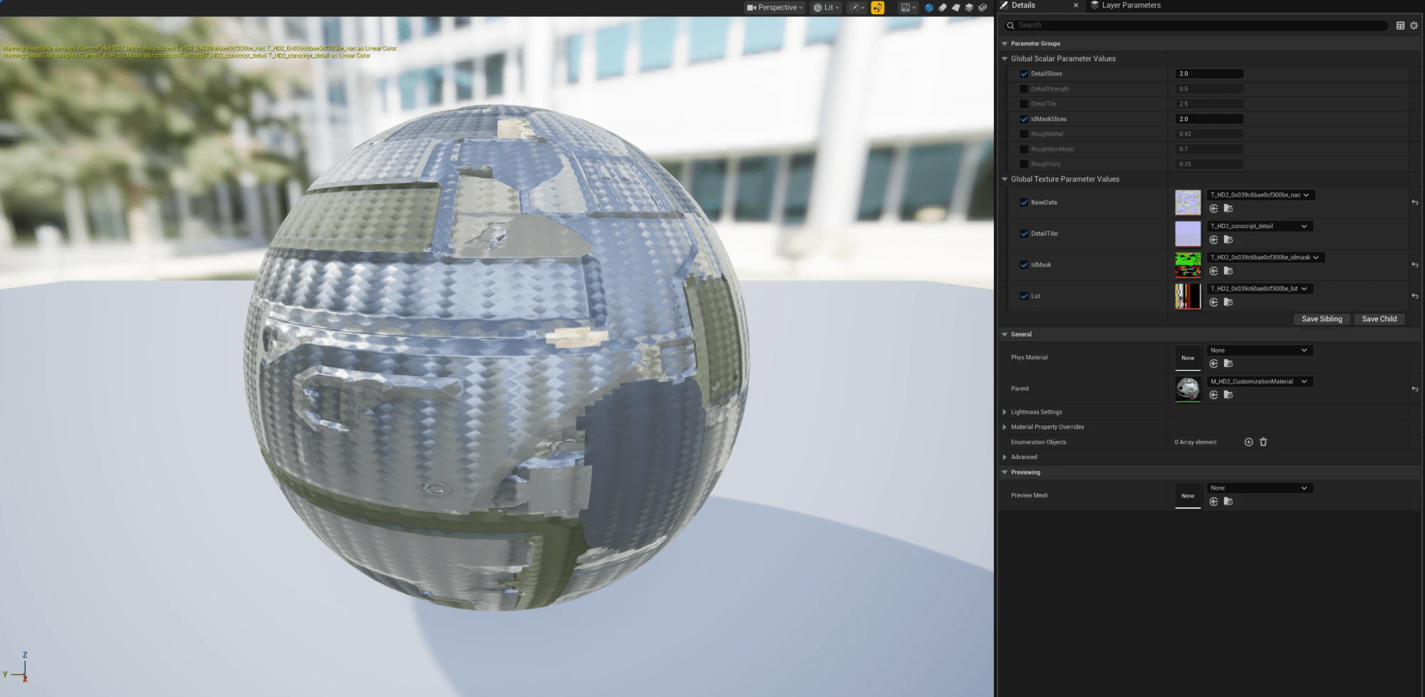
In the engine, this means: construct a single master material, with each unit as one material instance, those three images being set as texture parameters. Reverse-engineer once and the entire set is covered — there is no need to repeat the work per monster.
Four categories of non-standard materials
Not all materials undergo this procedural composition. Several material categories are laid out below alongside their respective pitfalls, for comparison:
| Material type | How to do it | Pitfall hit |
|—|—|—|
| Procedural armor (the majority) | Mask + palette lookup, one master material covers all, swap three images per unit | Texture purpose must be confirmed with a probe; inferring by appearance applies the wrong one (blotches) |
| Standard PBR | albedo + metallic packed, normal + AO + roughness packed | Packed channels must be split correctly |
| Recolor system | index image → palette ramp color lookup → team-color secondary shading | The index image was exported as albedo; applying it directly yields a uniform color block |
| Emissive / mask | base color + alpha clip + emissive overlay | Treating it as “wholly emissive” is incorrect |
Across the four, procedural armor and the recolor system share a common trap: the “textures” they extract are not colors but data images intended to be looked up in a table or used as indices. This is precisely why inferring by appearance is guaranteed to be wrong.
One inviolable rule paid for at cost
For any non-standard material, before construction begins, its shader must first be dumped and the sampler set examined to determine the type — never infer from appearance or filename.
The sampler names (e.g. “index emissive,” “palette color,” “subsurface transparency”) state directly which category the material belongs to and the purpose of each image. A single inspection of the sampler set is worth more than prolonged conjecture over thumbnails. This rule was paid for with three rounds of blotches.
Two classic traps: color space and compression
Once the algorithm is understood, two engineering details can still cause problems:
Double correction of color space. The palette stores sRGB colors, and the shader internally performs a manual sRGB→linear conversion. Consequently, in the engine, all these data images must be set to sRGB = off and then decoded manually in the material, to be equivalent to the game. If an image is set to sRGB = on, the engine corrects it a second time, and the result is uniformly too dark — a classic pitfall. The decision of whether an image should have sRGB enabled cannot rest solely on whether the shader decodes; its texture format must also be checked (a linear format is already linear — do not add another layer).
Texture compression must be differentiated by purpose. Images with exact values (masks, lookup tables) must under no circumstances be compressed — any block compression breaks region determination or palette color lookup; compressing a mask image garbles the region boundaries, compressing a palette ruins the colors. Data images and normal maps, by contrast, may use block compression — the error is acceptable and it saves three-quarters of the VRAM. Initially, for simplicity, everything was set to no compression, and one category of normal data images alone consumed over a thousand megabytes of VRAM; after classification by purpose, this fell to under three hundred megabytes.
6. Scaling up and concluding: from one to several hundred
Once a single unit worked end to end, the next task was to engineer it — rolling this pipeline out to ninety monsters plus three hundred fifty-six characters, each passing through the full “per-level FBX export → import → associate skeleton → mount LODs per level → assign material.” This stretch involves no spectacle, only the details of making the workflow robust:
- Checkpoint resume. Exporting a batch takes hours; the script must be interruptible and resumable — skipping what has already been exported rather than restarting from scratch each time.
- Always compare before overwriting. Before overwriting the old project with new assets, first produce a new-versus-old comparison table to confirm the material and LODs have not regressed; make a physical backup; then overwrite. This step echoes the previous article’s “dual-track parallel” — only validated artifacts enter the production project.
- Cross-project synchronization. The test project and the production project use two engines from different builds, with different engine build identifiers. Assets can be copied over directly, but after copying they must be re-validated — identical behavior under two engines cannot be assumed.
- Version-control submission in batches. A single submission of over two thousand files encounters connection timeouts, so it is split into batches of approximately one thousand each; the tool-source changes receive their own separate submission, kept apart from the assets, so the history remains clean.
7. Retrospective: what this reverse-engineering exercise actually taught
Distilling the entire article into a few points — not a technical checklist, but a mode of thinking when confronting a black box:
First, the material is not conjectured; it is read out by decompiling the game’s GPU shader. Applying a ready-made master material the moment a texture mapping appears failed three times. For any non-standard material, dump the shader first, examine the sampler to determine the type, and never infer from appearance.
Second, when two versions produce different results but the code is identical, compare the data rather than the code. The collapse defect was caught in this manner — the scale of the vertices and that of the bone bind matched only in part; this is invisible in the code, yet plainly evident in the matrix values.
Third, at times one need not understand the root cause; it suffices for the data to align. On the orientation obstacle, five rounds of conjecture about the root cause all proved wrong, then alignment of the bounding-box data resolved it in a single step. Understanding why has value, but when it yields no answer, do not expend effort in vain.
Fourth, per-level data comparison outperforms inspection of surface metrics. “Has five LOD levels” is correct, but a comparison of the per-level vertex counts reveals the discrepancy. This thread runs through the entire article — for collapse, compare the bounding box and matrix; for orientation, compare the bounding-box origin; for LOD, compare the per-level vertex counts. What truly enables one to see through the black box is not more sophisticated conjecture, but finer data.
Returning to the premise established at the outset: the previous article stated that gameplay validation can reuse existing assets and bring them up first. This article is its engineering-practice expansion — if one genuinely intends to bring external assets into an engine for prototype validation, the intervening pipeline is far from as straightforward as “merely importing”; it is a succession of “appears correct yet is in fact wrong” pitfalls. Resolving them one by one comes down not to luck, nor to a more capable tool (the tool is readily available on GitHub), but to stepping back and comparing at the data level at every obstacle.
8. An AI-Collaboration Retrospective: How This Was Actually Done With AI
About this section · Beginning with this article, “An AI-Collaboration Retrospective” becomes the fixed closing section of every piece in this series. It consistently answers four questions: what AI assisted with, where AI failed, how the human intervened, and how the matter was ultimately resolved. A series concerning “AI-native development” that displayed only the polished result and never recorded the genuine friction in the collaboration would be the least “AI-native” of all. This section is precisely what distinguishes this series from an ordinary technical blog.
This is an “AI-native development in practice” series, so in the interest of transparency: much of the reverse-engineering, debugging, and batching of the pipeline above was conducted in collaboration with AI — and this article itself (the text, the figures, the publishing) is likewise a product of human–AI collaboration. Below are several pitfalls the AI encountered this time, and how the human intervened to compensate.
Pitfall 1: The AI sought to capture the engine screenshots itself but could not even launch the application. The engine screenshots in this article were originally intended to be captured by the AI via desktop automation. It became stuck at the first step — the permission layer repeatedly reported “application not found,” rejecting every process name, window title, and variant attempted. The root cause is that this category of automation recognizes only applications registered with the system, and this engine’s executable was not among them. Resolution: the human took over the screenshot capture directly. The lesson is plain — when an automation path simply does not function in a given environment, do not contend with the tool; delegating that single step to a human is frequently a matter of seconds. The AI required seven or eight rounds to confirm the path was a dead end; the human obtained the shots in thirty seconds.
Pitfall 2: The AI can see an image but cannot save it. Screenshots were pasted into the conversation by the human; the AI could “see” the content and compose captions from it, but no tool could convert an image in the conversation into a file on disk — and both embedding into the article and uploading for publishing require a file on disk. Clarifying this boundary took several exchanges. Resolution: the human manually saved the images into a designated directory, and the AI then read and processed them from disk. This exposes an often-overlooked collaboration boundary: the AI “seeing” and the AI “possessing” are two distinct things. Seeing serves understanding; possessing serves processing — and that gap must be bridged by a human.
Pitfall 3: The AI assumed it had to redo work already completed. The English translation was delegated to a subtask, which was interrupted midway. The AI’s initial instinct was “interrupted = unfinished, must redo,” and it was about to re-translate — until a disk check revealed the subtask had in fact completed and saved the entire English version before being interrupted. Resolution: check the state first, then decide on the action. The lesson: “the process was interrupted” does not entail “the result does not exist” — before redoing anything, confirm the current state rather than substituting intuition for verification. This is precisely a replay of the article’s own methodology: do not rely on impression, examine the data (here, the actual artifact on disk).
Pitfall 4: Non-ASCII filenames and a batch script, in a classic conflict. The first version of the image-upload script used a data structure to map “Chinese filename → upload name,” and at runtime raised “illegal characters in path,” failing on the Chinese filenames. Resolution: switch to an approach that does not depend on that structure — explicit paired arrays. This is a long-standing engineering problem (non-ASCII paths combined with certain APIs), but it serves as a reminder: AI-written scripts are generally sound on the happy path; the real pitfalls reside in boundary inputs — Chinese names, special characters, and empty directories are the items to watch specifically.
Pitfall 5: The images uploaded, but some did not make it into the article. The figures are of two kinds (diagrams and engine screenshots); after publishing, a check showed only the diagrams entered the body — the engine-screenshot kind did not render. The peculiar aspect: when the parsing logic was reproduced line by line in an interactive session, all eleven images generated correctly; but the moment it ran as a complete script file, only five remained. Repeated scrutiny of the code revealed no difference — because the difference did not lie in the code logic at all. It was finally pinned down by comparing the actual artifact (reading the real published content and counting how many images, and whether captions, it contained): the problem was the script file’s encoding — the publish script was not saved with a BOM, and this machine’s PowerShell reads script files in the local code page by default, so the bytes of one line of a Chinese comment were misread and “consumed” the block of processing logic immediately following it. Adding the correct encoding marker to the script caused all eleven images to land at once. This is the same lesson as the collapse defect in the article, staged a second time: when result and expectation disagree but the code shows nothing wrong, compare the artifact and check the environment rather than merely comparing the code. Here the “artifact” was the published image count, and the “environment” was the script file’s encoding — neither resides in the code itself.
These five pitfalls reduce to a single statement: the AI undertook a great deal of repetitive, tedious, mechanizable work (reverse-engineering, batching, translating, drawing, scripting), but every “environment boundary” and “state judgment” hurdle required a human to intervene with precision. The efficiency of the collaboration lies not in the AI performing everything, but in the human knowing at which step to take over — taking over the screenshot capture where it can be done manually, taking over the saving where files must land, prompting a state-check where one is due. That, too, is a discipline “AI-native development” must practice.
This is the second installment of the in-practice series. In the next installment, the map from the panorama article will be followed, continuing toward combat, enemies, and the AI Director.
A final note on the premise: this pipeline was built to learn the engine art workflow and validate prototype feasibility; the tool derives from community open source, the work consists of source customization, and it does not involve circumventing game protection. External assets here are merely temporary placeholders for the validation phase; upon reaching the product phase, they should be replaced by self-made assets — they were never the finish line. The path that leads to the finish line is what this article seeks to leave behind.