
This is a linear walkthrough: follow one mesh asset through Nanite’s full data flow — how it’s processed offline into Nanite format (resource processing), and how that data becomes pixels on screen at runtime (the render pipeline).
Depth is implementation-level, with
file:linereferences at key points (based on a UE 5.7 source build ofE:/Project/UE; line numbers may drift across versions). To drill into any one mechanism, see the matching question in *Nanite, in Q&A* (marked Qn in the text).
Nanite in one line: it rewrites rendering cost from “how many triangles are in the scene” to “how many pixels are on screen.” To deliver that, it splits the work in two — half offline (preprocess the high-poly into a streamable, continuous-LOD compressed dataset), half on the GPU at runtime (self-driven culling, LOD selection, rasterization, shading). This article walks those two halves in order.
Nanite’s pipeline has two stages, each with an overview figure. First the offline stage — processing the high-poly into streamable, continuous-LOD compressed data, with everything the runtime needs to pick LOD prepared in advance:

The runtime overview is at the start of part two.
The entry is NaniteBuilder.cpp: the imported mesh data enters FClusterDAG, calls ReduceMesh per mesh (:680) to build the LOD hierarchy, then BuildFallbackMesh (:724) for the fallback mesh, and finally Encode (:936) to compress and write out. Below, each step unpacked.
① Cut clusters: chop the mesh into ~128-triangle clusters

The first step cuts the whole mesh into clusters of about 128 triangles each (FCluster::ClusterSize = 128, Cluster.h:243). Why 128: it’s a GPU-friendly granularity, hard-bound to the 7-bit triangle index in the VisBuffer (2^7 = 128, see Q1/Q12).
The cut isn’t by a spatial grid (which would split one continuous surface across clusters and fragment boundaries) but by building triangle adjacency into a graph and partitioning it: triangles are nodes, shared edges are connecting edges, and the goal is “each block ≤128 nodes, minimal total cut-edge weight.” In the source, ClusterDAG.cpp‘s initial partitioning has two partitioner paths to choose from (:113/:132):
FBVHCluster: spatial-BVH-based partitioning;FGraphPartitioner: graph-partitioning-based, calling METIS.
The main path takes graph partitioning. When building the graph, edges are added between adjacent triangles with weight 4 * 65 (ClusterDAG.cpp:160, the cost of a shared edge), then AddLocalityLinks mixes in Morton spatial-locality links (:164), and finally PartitionStrict (:170) recursively bisects until all blocks are ≤128.
There’s a commonly misunderstood point here (Q25): METIS is just a building block called to do “one 2-way min-cut bisection”; the outer “recurse to ≤128 + deterministic sort + locality” is all wrapped by Epic (GraphPartitioner.cpp‘s RecursiveBisectGraph, Ranges.Sort() for determinism, BuildLocalityLinks). meshoptimizer isn’t used because its meshlet partitioning has a different goal (vertex reuse + cone cull, not the min-cut serving later simplification).
Why cluster quality matters: cluster boundaries get frozen during later simplification (next step), and the shorter and fewer the boundaries, the more interior is left to simplify — cut quality directly determines whether LOD can climb.
② DAG simplification: the data structure of continuous LOD

After the leaf clusters (LOD0) are cut, ReduceMesh (ClusterDAG.cpp:639-860) iterates upward to build the hierarchy:
leaf clusters (LOD0) → group 8~32 adjacent clusters → simplify the group to ~half the triangles → re-split into 4~16 new clusters (next level up) → repeat to the rootWhy a DAG and not a tree: a parent cluster is the merge-and-simplify product of several children, and grouping boundaries reshuffle at every level, so parent-child is many-to-many (and many-to-many is a directed acyclic graph). In the source, FClusterRef can carry an InstanceIndex to support Assembly multi-instancing, and RootClusterGroup (Groups.Last()) is the unique root (Q4).
Simplification uses QEM (quadric error metric): FMeshSimplifier::Simplify returns MaxErrorSqr (Cluster.cpp:549-743) — the worst-case squared distance from any point to the simplified mesh; sqrt and inverse-scaled back to the original coordinate system, it’s the cluster’s LODError. Attributes are weighted: normals 1.0, UVs by area, bone weights 0.

Two guarantees (Q13) make this LOD correct at runtime:
- Boundary locking (crack-free): when simplifying a group, iterate edges with
ExternalEdges[i]≠0(shared with other clusters) andLockPosition()both endpoints (Cluster.cpp:660-675). Adjacent clusters simplify independently but the shared edge stays vertex-aligned — no cracks. And grouping is staggered per level — this level’s boundary falls inside a group at the next and gets simplified, so “every boundary is eventually simplified away” yet “any single level doesn’t crack.” - Error monotonicity: forces
ParentLODError = max(ParentLODError, SimplifyError)(ClusterDAG.cpp:1070), guaranteeing error grows toward the top of the DAG. Otherwise the runtime LOD “cut” would self-contradict (parent and child both selected → overlap/holes).
The product of this step is a whole DAG, each cluster carrying a geometric error and a bounding sphere — everything the runtime needs to “pick LOD by screen-projected error” is prepared.
③ Quantization encoding: how positions compress, how precision is auto-decided

Geometry’s real bottleneck is data volume (memory/bandwidth/streaming), so Nanite’s overall philosophy is “quantize instead of storing floats, derive instead of storing.” Positions use a uniform quantization grid (NaniteEncode.cpp:191-345 CalculateQuantizedPositionsUniformGrid):
IntPosition = round(Position × 2^P) // P = Position Precision, step 2^-P cmEach cluster stores its integer min-corner QuantizedPosStart + per-axis bit width QuantizedPosBits (the CeilLogTwo of the range), and vertices store only unsigned offsets from the min-corner — globally uniform precision, locally adaptive bit width.
Precision P defaults to Auto (PositionPrecision = MIN_int32), decided in four steps (Q24):
- Density heuristic: mean log2 of leaf-cluster bounding-box size →
P = 7 - round(AvgLogSize)(:224). Leaf clusters are a constant 128 triangles, so smaller leaf = denser = finer step. - Auto floor
AUTO_MIN_PRECISION = 4(step 1/16 cm,:231) — lower precision saves little package size yet exposes quantization staircases. - Global clamp to [-20, 43].
- Auto-downgrade on overflow: if any axis of any cluster exceeds 2^21-1, halve the scale and decrement P, looping until everything encodes (
:250-271).
Why 21 bits/axis: 21*3 = 63 < 64 (NaniteDefinitions.h:165) — the three quantized coordinates must fit a 64-bit budget. Engineering implication: step 4’s downgrade is mesh-wide, and one abnormally large cluster drags the whole mesh’s precision down — so don’t merge wildly-different-scale geometry into one asset.
Normals are likewise quantized (octahedral, two components, up to 15 bits each, NaniteDefinitions.h:168); tangents aren’t stored by default, derived at the pixel stage at runtime (see the render section / Q16).
④ Vertex strip encoding: not indirect indices

Intra-cluster triangle indices are not the naive “3 32-bit absolute indices per triangle” but a triangle strip + Ref/New vertex variable-length encoding (NaniteEncodeTriStrip.cpp:141 UnpackTriangleIndices):
- New vertex: a new vertex, implicitly numbered in order, costing no index bits;
- Ref vertex: back-references a prior vertex, storing a 5-bit relative offset (
BaseVertex - (IndexData & 31u), back-referencing up to 32).
FStripDesc.NumPrevRefVerticesBeforeDwords / NumPrevNewVerticesBeforeDwords (Cluster.h:195) are per-dword prefix counts, located on the fly with CountBits. There’s also build-time FVertexArray::FindOrAddHash (Cluster.h:103) for intra-cluster vertex dedup.
Where it saves: advancing the strip by one triangle usually adds just 1 New vertex and back-references the other 2, so most vertices cost 0 index bits and only reused ones cost 5 bits. This encoding is restored at runtime by GPU transcode using the same unpack logic (Q25).
⑤ Paging: resident Root + on-demand Streaming
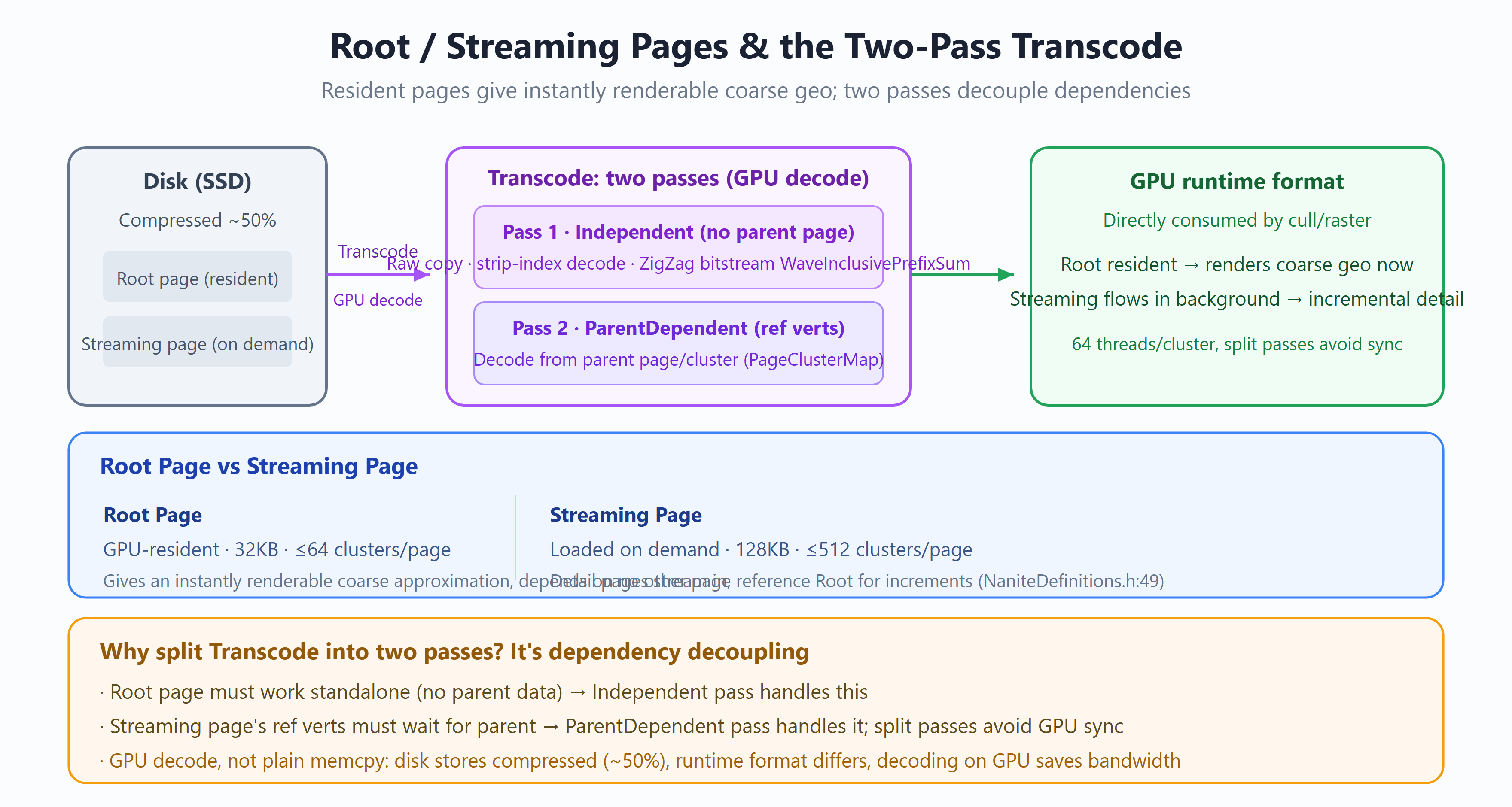
Encoded clusters are packed into pages by Morton order + LOD level (NaniteEncodePageAssignment.cpp), in two kinds (NaniteDefinitions.h:49):
- Root Page: resident in GPU memory, 32KB, ≤64 clusters/page. Depends on no other page, so the asset can render a coarse geometry approximation the moment it loads;
- Streaming Page: streamed on demand, 128KB, ≤512 clusters/page. Detail pages referencing the Root for increments.
Why two kinds: all-on-demand would mean no geometry on the first frame an asset enters view (pop/hole); resident Root pages guarantee “coarse shape first, detail filled in after,” the foundation of Nanite’s “something to render at any distance.” On disk a page is a further-compressed bitstream (lossless, ~50%), decoded on the GPU (saving streaming bandwidth, the real bottleneck).
⑥ Fallback Mesh + Cook

The build also produces a fallback mesh (NaniteBuilder.cpp:724 BuildFallbackMesh) — a traditional mesh auto-simplified from the source, rendering as a stand-in on platforms without Nanite, and by default serving complex collision and lightmap baking. Quality is controlled by FallbackTarget / FallbackPercentTriangles / FallbackRelativeError (FMeshNaniteSettings, EngineTypes.h) (Q22).
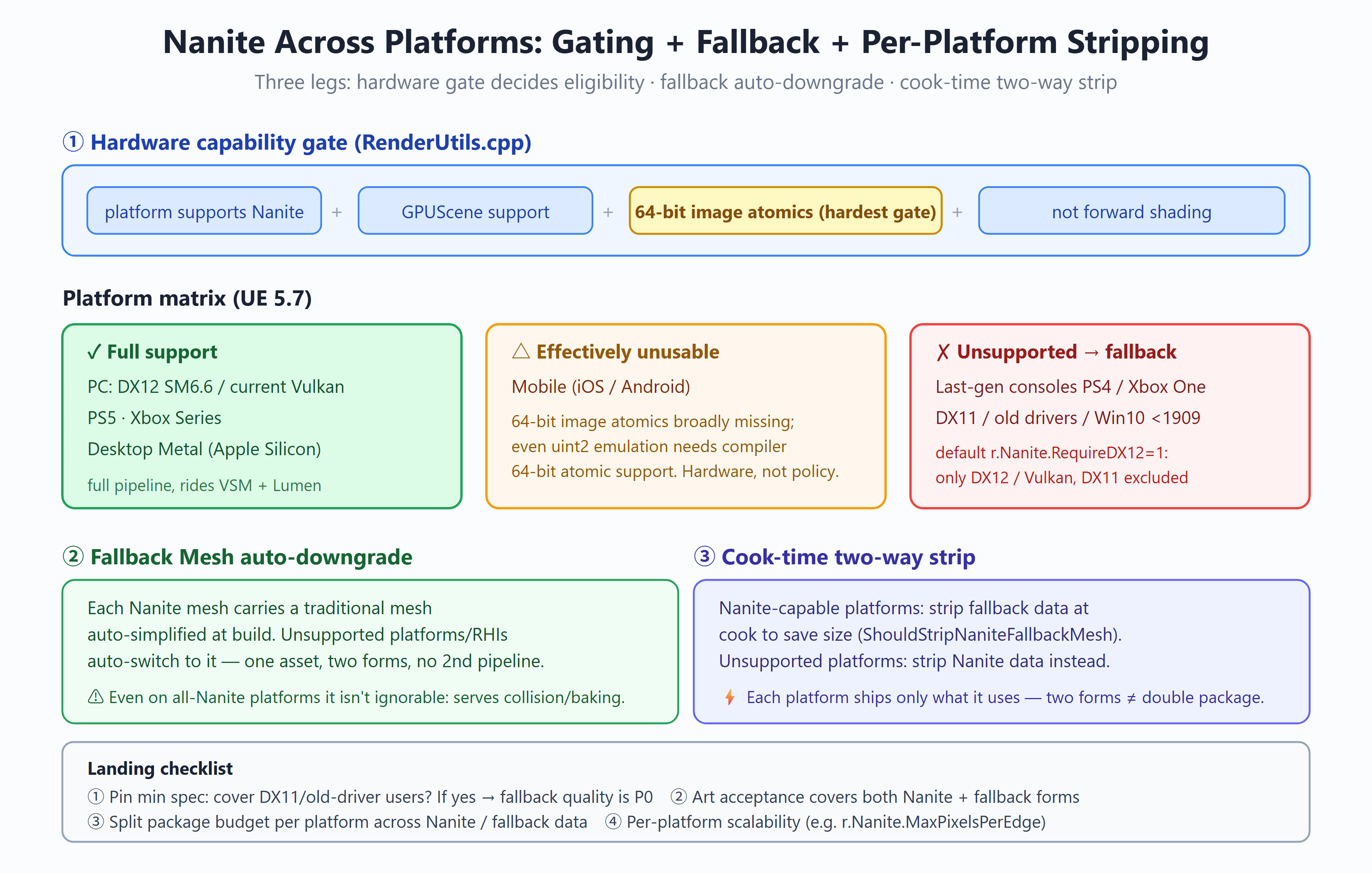
Two-way strip at cook time (Q23): Nanite-capable platforms strip the fallback data to save package size (ShouldStripNaniteFallbackMesh, StaticMesh.cpp:203); unsupported platforms strip the Nanite data instead. Each platform ships only what it uses — two forms isn’t double the package.
At this point the offline output is: a compressed, paged cluster DAG (Nanite data) + a fallback mesh, written into the .uasset.
The runtime is entirely GPU-driven — culling, LOD selection, rasterization, shading all strung together on the GPU via ExecuteIndirect, with the CPU submitting once and never reading back. The scheduling main flow is in NaniteCullRaster.cpp‘s DrawGeometry (around :6300). First the runtime overview (dark boxes are Nanite’s three core innovations; the bottom points back to which offline step each consumes):

⑦ Streaming + Transcode: turn compressed pages into usable geometry
Picking up the offline paging: at runtime, streaming requests (FStreamingRequest, NaniteStreaming.ush) pull the needed Streaming pages from disk into VRAM by camera demand. What arrives is a compressed bitstream, decoded on the GPU (Transcode, NaniteTranscode.usf) in two passes (Q14):
- Independent pass: handles data with no parent-page dependency — raw copy, Strip index decode, positions via a ZigZag bitstream +
WaveInclusivePrefixSum; - ParentDependent pass: handles cross-page referenced vertices, decoded from the parent page (via
PageClusterMap).
The two passes split for dependency decoupling — Root pages decode entirely in the Independent pass (they must work independently), while Streaming’s referenced vertices wait for the parent page, avoiding GPU sync within one pass. 64 threads handle one cluster.
This step connects offline ④ (strip encoding) and ③ (quantization): strip indices and ZigZag deltas are restored here into runtime-usable vertices.
⑧⑨ Instance culling: PrimitiveFilter + InstanceCull
GPUScene holds all instances’ transforms resident. The first two of DrawGeometry‘s five-stage schedule (NaniteCullRaster.cpp):
- PrimitiveFilter (
:3969): generates a GPU-side filter mask by HiddenPrimitives / ShowFlags; - InstanceCull (
:4364): per-instance frustum + HZB occlusion culling (InstanceCull_CS, 64 threads/group), writing a candidate queue; occluded instances are recorded intoOccludedInstances(deferred recheck, see ⑬). Large worlds can optionally use Instance Hierarchy (5.7) for hierarchical culling.
⑩ persistent threads traverse the DAG: pick the LOD cut

This is Nanite’s core runtime innovation. Picking LOD is essentially finding a “cut” on the DAG — the ring of clusters the cut passes through is the LOD drawn this frame. The criterion projects a cluster’s geometric error to screen pixels (NaniteClusterCulling.usf:322):
bool bVisible = ProjectedEdgeScale > UniformScale * LODError * NaniteView.LODScale;Descent stops once the projected error drops below ~1 pixel (fine enough), else it expands into finer clusters down the DAG.
Traversal uses persistent threads + a work queue (NaniteCullRaster.cpp:4238): launch thread groups roughly equal to all CUs, each using InterlockedAdd to atomically steal candidate nodes from QueueState — if not SmallEnoughToDraw, push children back onto the queue for other threads to expand; if it is, write to the visible-cluster buffer. Entirely GPU-driven, no CPU readback (Q5).
Why no popping: the criterion is a continuous function (smooth with distance), one cluster (~128 triangles) swaps at a time, and old/new cluster boundaries are strictly aligned by LockPosition (②) — it’s continuous LOD, not discrete tier switching.
The
LODErrorused for LOD selection (from offline ②’s QEM) and the bounding sphere are exactly what the offline build prepared; monotonicity (②) keeps this cut well-defined.
⑪⑫ Hybrid software/hardware rasterization → VisBuffer64

The selected visible clusters get rasterized. Nanite routes by triangle screen size (the criterion computed during culling, NaniteClusterCulling.usf:330):
- Small triangles → software rasterizer (compute): sidesteps the hardware 2×2 quad’s overshading (a tiny triangle’s quad utilization bottoms out at 1/4); fully incremental edge functions (pure adds, no mul/div); single-triangle bbox cap of 64×64 pixels (
NaniteRasterizer.ush:73); - Large triangles → hardware rasterizer (
FHWRasterizeVS/MS/PS, Mesh Shader in 5.7): fixed-function units fill faster in parallel.
RasterBinning (NaniteCullRaster.cpp:5619) bins clusters by material flags/size/depth, routing to the soft/hard paths.

The software rasterizer owns watertightness: vertices in 4.8 fixed-point, half-edge constants in 8.16 fixed-point (NaniteRasterizer.ush:88-106); integer math is exact, so adjacent triangles’ shared-edge edge functions are bit-identical, no cracks or double-writes; a Top-Left fill rule adjudicates on-edge pixels (Q3).
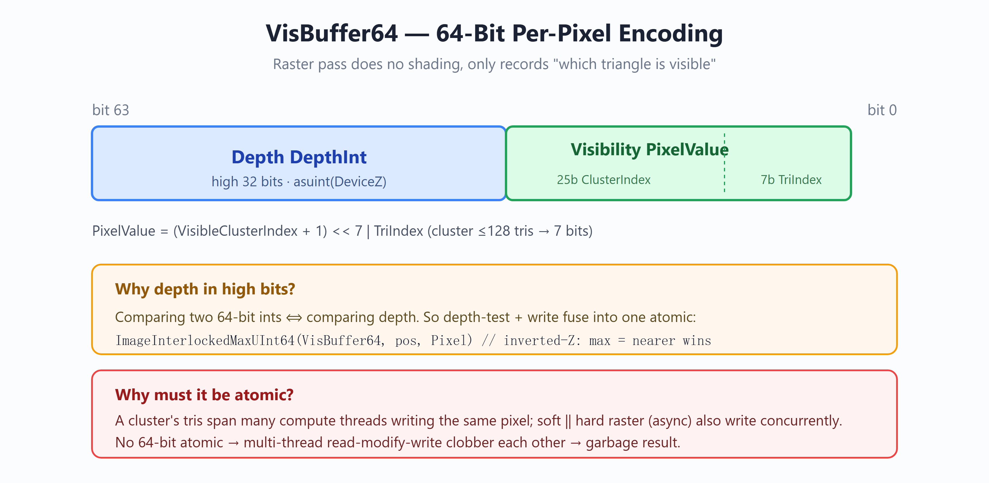
Both raster paths shade nothing, writing only “who is visible” into the 64-bit-per-pixel VisBuffer64 (NaniteWritePixel.ush:30):
const UlongType Pixel = PackUlongType(uint2(PixelValue, DepthInt));  // high 32 bits depth + low 32 bits visibility ID
ImageInterlockedMaxUInt64(OutBuffer, PixelPos, Pixel);               // one atomic = depth test + write
With depth in the high bits, one InterlockedMax performs the depth test and the write together (under inverted-Z, greater = nearer). It must be a 64-bit atomic, because a cluster’s triangles write concurrently across threads and soft/hard rasterizers write the same pixel via async compute (Q1). This atomic is also why Nanite hard-depends on 64-bit image atomics and is effectively unusable on mobile (Q23).
⑬ Two-pass occlusion culling

Occlusion culling needs an HZB (depth pyramid), and the HZB needs rasterization first — a circular dependency. Nanite breaks it with two passes (Q6):
- Main pass: cull and rasterize the visible part with last frame’s HZB; instances judged occluded aren’t discarded but recorded into
OccludedInstancesfor deferred recheck; - Rebuild the HZB: build a new HZB from this frame’s rasterized depth (
BuildHZBFurthest); - Post pass: retest only the deferred-recheck instances against this frame’s new HZB, rasterizing any that are overturned.
By frame-to-frame coherence, most objects are culled correctly with one frame’s HZB, and only a few occlusion-boundary ones reach the Post pass. On a camera cut, last frame’s HZB is invalid and a raster spike appears; 5.7 mitigates it with HZB priming.
⑭ ShadeBinning → GBuffer: shade each pixel once

Shading happens only after all geometry is written and each pixel’s unique visible triangle is settled. This is the essential difference from traditional deferred: traditional deferred shades during the geometry pass (occluded fragments too — overdraw), while Nanite defers shading until visibility is settled, so occluded pixels never enter shading (Q15).
ShadeBinning’s three stages (NaniteShadeBinning.usf):
- COUNT: read VisBuffer + ShadingMask for each pixel’s material bin, tally pixels per bin with
WaveActiveCountBits; - RESERVE: allocate contiguous pixel storage per bin + generate indirect dispatch arguments (
bNoDerivativeOpsdecides per pixel vs. per 2×2 quad); - SCATTER: compute each pixel’s exact write offset and scatter it into its bin.
Result: each material runs one compute shader, dispatched over only the visible pixels it covers, so shading cost = screen pixels × a constant, fully decoupled from the product of triangle count and material count.

The shading stage looks up the triangle from the VisBuffer and decodes attributes. Tangents are derived on the fly here (not stored offline, as ③ noted): cross products of the normal + triangle edges + UV gradients compute the tangent basis (Christian Schüler’s method, NaniteAttributeDecode.ush:610) — trading compute for memory. Normals are decoded from quantized values (UnpackNormal).
The shading output is written into a standard GBuffer, from which it joins UE’s deferred render pipeline.
Into UE5 rendering: VSM / Lumen

Nanite’s GBuffer isn’t the end — it feeds the whole UE5 lighting pipeline (Q10):
- VSM (Virtual Shadow Maps): paged high-resolution shadows, designed precisely for Nanite’s geometric density; also reuses Nanite’s two-pass occlusion (paged HZB);
- Lumen (global illumination): shifts to HWRT in 5.6/5.7, needing a real BLAS.

But Nanite geometry is compressed dynamic LOD while a ray tracing BLAS needs definite triangles — a conflict. The solution is StreamOut: FNaniteStreamOutTraversalCS (NaniteStreamOut.cpp:65) selects clusters on the DAG by an independent cut error, exporting a definite VB/IB to build the BLAS, with ray-tracing LOD decoupled from raster LOD (usually coarser). This is another use of the offline DAG data at runtime — one DAG, rasterization takes one cut, ray tracing takes another coarser cut. 5.7 adds RT Streaming, CLAS, and more (Q19).
Looking back at the whole pipeline, offline and runtime aren’t two disjoint stages but one set of offline preparation, runtime consumption:
- cluster DAG + per-cluster QEM error (②) → persistent threads project the error to screen pixels to pick the LOD cut (⑩)
- boundary locking + error monotonicity (②) → guarantees the selected cut doesn’t crack or overlap (⑩’s no-popping prerequisite)
- quantized positions + strip encoding (③④) → Transcode restores usable vertices on the GPU (⑦)
- Root/Streaming paging (⑤) → streaming pulls pages on demand, Root guarantees coarse geometry on the first frame (⑦)
- fallback mesh (⑥) → downgrade rendering on unsupported platforms (the traditional path outside ⑦)
- one DAG → rasterization takes one LOD cut, ray tracing StreamOut takes another coarser cut (⑩ / Lumen)
To close in one line: Nanite turns “geometric-complexity management” from a runtime manual problem into a pipeline of “offline compression + runtime GPU-driven consumption” — offline splits the high-poly into streamable, continuous-LOD compressed data with everything needed to pick LOD, and at runtime the GPU traverses, culls, rasterizes, and shades itself, ultimately tying rendering cost to screen pixels alone.
Part Three below unpacks the “why this design” of each step into 25 Q&A items (the Qn markers above are the question numbers); each has a written answer, source citations, a scoring rubric, red flags, and follow-up probes.
Core Machinery (Q1–Q6)
<a name=”q1″></a>
Q1. What’s packed into VisBuffer64? Why this layout? Why must it be atomic?
Model answer:
Nanite’s rasterization stage does no material shading at all — it answers exactly one question: for each pixel on screen, which triangle is finally visible. That answer lives in a buffer called VisBuffer64, 64 bits per pixel.
The layout is (NaniteWritePixel.ush:30):
const UlongType Pixel = PackUlongType(uint2(PixelValue, DepthInt));- High 32 bits = depth (DepthInt): the float depth
asuint(saturate(DeviceZ))reinterpreted as an integer. - Low 32 bits = visibility (PixelValue):
(VisibleClusterIndex+1)<<7 | TriIndex— i.e. the high 25 bits are the visible cluster index, the low 7 the triangle index (a cluster holds at most 128 triangles, exactly 7 bits).
Why depth in the high bits: comparing two 64-bit integers is then equivalent to comparing their depths. So one atomic op suffices for the write (NaniteWritePixel.ush:31):
ImageInterlockedMaxUInt64(OutBuffer, PixelPos, Pixel);InterlockedMax keeps the larger value — because UE uses inverted-Z (near = large), the greater depth is the nearer one. This single atomic performs the depth test and the write together: if the new fragment is nearer, its 64-bit value is larger and the whole value (depth + visibility ID) is replaced as one; otherwise the old value stays. Depth test and visibility write are fused — there is no separate depth pass.
Why it must be atomic: all triangles of a cluster are rasterized across many compute threads simultaneously, and they can hit the same pixel at once; moreover Nanite’s software and hardware rasterizers can write the same buffer concurrently via async compute (Platform.ush:1350-1364 defines both a native uint64 and a uint2-emulated implementation). Without a 64-bit atomic, the read-modify-writes of multiple threads clobber each other and the result is corrupt.
The essential payoff: pixels occluded at the raster stage never enter material shading — they get overwritten in the VisBuffer by a nearer fragment, and shading happens only after all geometry is written (see Q15). This eliminates the shading waste of overdraw, one of the cornerstones of Nanite’s “rendering cost decoupled from geometric complexity.”
✅ Scoring rubric (by tier)
- 〔Pass〕 A candidate roughly says: *”VisBuffer stores depth and an ID per pixel, recording which triangle is visible; the raster stage doesn’t shade.”*
→ Why it scores: catches the core intent — “deferred shading + store visibility only.” Right direction.
- 〔Good〕 *”Depth goes in the high 32 bits, so one
InterlockedMaxcomparing 64-bit integers does the depth test and the write at once; under inverted-Z, max means the nearer one wins.”*
→ Why it scores: understands the bit layout *serves* the atomic merge — it isn’t arbitrary. The key “knowing why.”
- 〔Strong〕 *”It must be atomic because a cluster’s triangles rasterize in parallel across compute threads, and soft/hard rasterizers can write the same pixel concurrently via async compute; and the whole design keeps occluded pixels out of material shading, eliminating overdraw’s shading waste.”*
→ Why it scores: explains both concurrency correctness and what the design saves.
- 〔Bonus〕 *”The low 7 bits are the triangle index (≤128 tris/cluster, exactly 7 bits), the high 25 the cluster index; the
+1reserves 0 as an empty-pixel sentinel; platforms without native 64-bit atomics use uint2 emulation.”*
→ Why it scores: down to the bit level + aware of platform fallback — has actually read the source or built a similar system.
⛔ Red flags (what’s wrong / why / what’s correct):
- “Nanite draws geometry with a traditional depth buffer + many draw calls.”
– What’s wrong: Nanite bypasses the traditional primitive pipeline entirely, using GPU-driven compute rasterization + a single VisBuffer — there is no “per draw call.”
– Correct: one dispatch rasterizes all visible clusters into the VisBuffer.
- “Shade the material right there at rasterization and write it in.”
– What’s wrong: that degenerates back to traditional deferred — occluded fragments get shaded too (overdraw).
– Correct: rasterization writes only “who’s visible”; shading is deferred until all geometry is settled, then done once per material via binning (Q15). Conflating VisBuffer with GBuffer is the most common “half-understood” tell.
- “Depth in one image, visibility ID in another, written separately.”
– What’s wrong: the two writes can’t be atomically bound — thread A’s depth wins but thread B’s ID gets written, leaving depth and ID inconsistent (wrong visibility).
– Correct: they must be packed into one 64-bit value and written in a single atomic, so the “winning depth” and “its ID” land together.
🕳️ Plausible-but-wrong traps (sound right, only half-understood):
- “Using atomicMax for the depth test is common (early GPU particles did it too).” — The half-truth: atomicMax for pure depth is nothing new; Nanite’s essence is packing the visibility ID into the low bits of the same 64-bit integer with depth in the high bits, so one atomicMax solves “depth compare” and “visibility binding” together. Not mentioning the *packing* misses the point.
- “VisBuffer is just a kind of G-Buffer.” — The half-truth: backwards. A G-Buffer stores material attributes needed for shading (already partly computed); VisBuffer stores a visibility reference (who’s visible, not yet shaded). VisBuffer → (decode + Shade Binning) → G-Buffer are two stages.
- “Depth in the high bits is for precision.” — The half-truth: it’s not precision, it’s making the integer ordering == the depth ordering, so atomicMax’s semantics exactly equal the depth test. Put it in the low bits and that property is gone.
🔍 Follow-up probes (the interviewer drills down):
- Q: Why must depth be in the high bits — can’t it go low? A: No.
InterlockedMaxcompares the whole 64-bit integer; only with depth in the high bits does integer ordering equal depth ordering, making max equivalent to a depth test. With depth low, the cluster index dominates the comparison and the result is wrong. - Q: Why is a cluster ≤128 triangles — is that tied to the 7 bits here? A: Yes. The low 7 bits encode the triangle index, 2^7 = 128, matching the build-time ≤128 triangles per cluster (Q12) — the bit layout and cluster size are co-designed.
- Q: Is there a cap on simultaneously visible clusters? A: Yes — the high 25 bits → ~33 million clusters; huge scenes stream the invisible ones out.
- Q: Mobile / hardware without 64-bit atomics? A:
UlongTypedegrades to uint2 emulation (Platform.ush:1352), but the compiler still needs 64-bit atomic instructions — one of the underlying reasons Nanite’s mobile support stayed limited for so long.
Probe prep: if asked “what does this design cost” — see Q20: it locks in “one value per pixel,” so no translucency, and the depth function can only be Greater-Or-Equal.
🔧 Senior perspective (addendum)
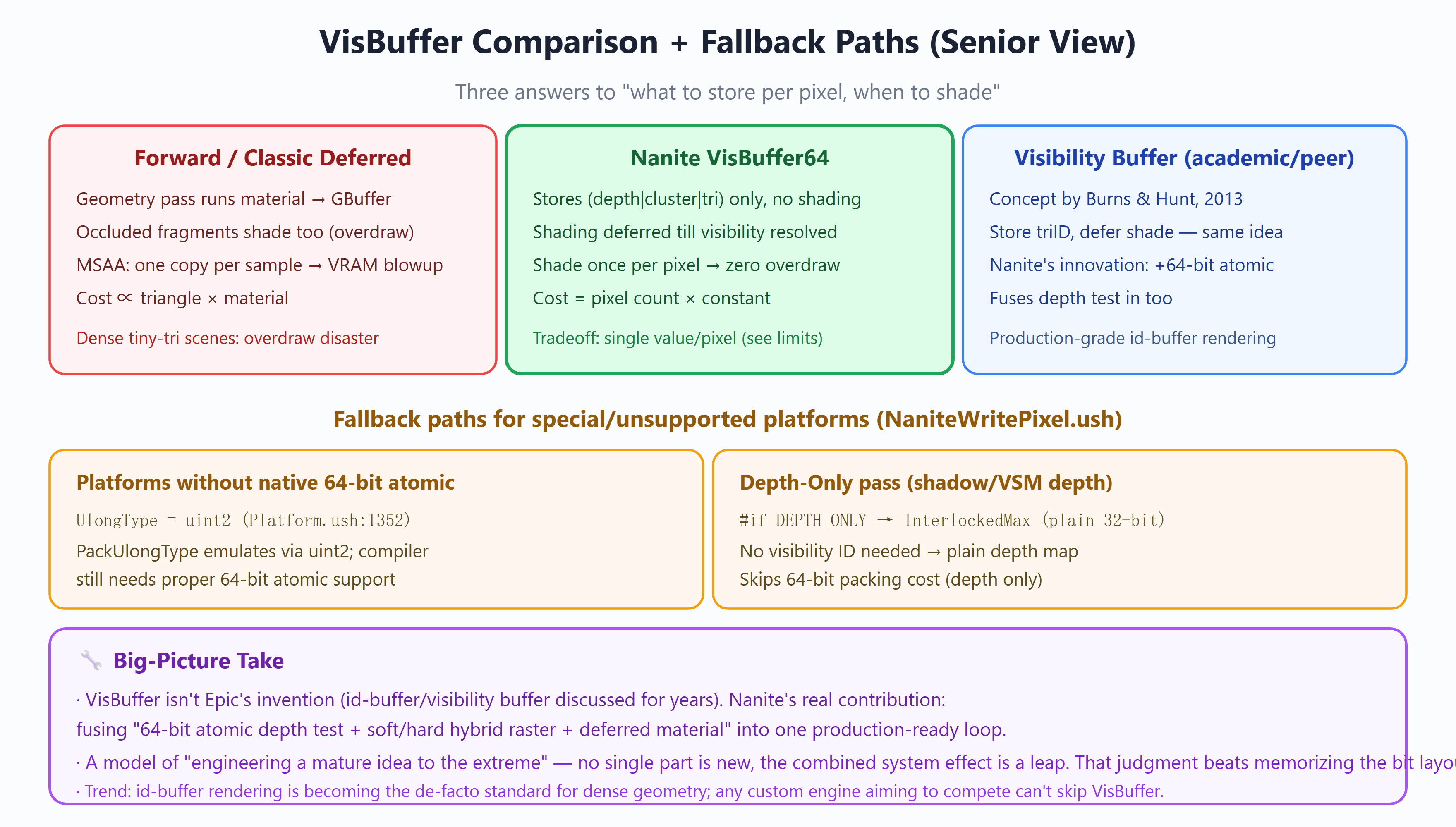
The macro view: VisBuffer isn’t Epic’s invention — visibility-buffer / id-buffer rendering was proposed by Burns & Hunt in 2013 (“The Visibility Buffer”). Nanite’s real contribution isn’t “the idea of storing a triangle ID,” it’s combining 64-bit atomic depth-test merge + hybrid software/hardware rasterization + deferred material shading into one production-grade loop. No single piece is new; the system effect of the combination is the leap. I’d argue this question really tests that judgment — recognizing “what is engineering of an existing idea vs. what is original” is worth more than reciting the bit layout. As a trend, id-buffer rendering is becoming the de facto standard for high-density geometry.
Easily-missed details:
- The low 7 bits are the triangle index, exactly matching “≤128 triangles per cluster” (Q12) — the bit layout and the build-time cluster size are co-designed, not a coincidence.
- The high 25 bits of cluster index mean there’s a cap on simultaneously visible clusters (~33 million); huge scenes stream the invisible ones out.
- That
+1in(VisibleClusterIndex+1): reserves 0 as an “empty pixel” sentinel, avoiding confusion between cluster 0 and an empty pixel.
On special / unsupported platforms (from the source):
- Platforms without native 64-bit atomics:
UlongTypedegrades touint2emulation (Platform.ush:1352), but the compiler still needs 64-bit atomic instructions — so genuinely old hardware / some mobile GPUs limit Nanite, one of the underlying reasons its mobile support lagged. - Depth-only path: when shadows / VSM depth need only depth and no visibility ID, it takes
#if DEPTH_ONLY → InterlockedMax(plain 32-bit), skipping the 64-bit packing cost (NaniteWritePixel.ush:27).
How to optimize / diagnose: use r.Nanite.Visualize‘s overdraw mode to confirm VisBuffer write pressure; if a region’s overdraw is high, it’s usually many overlapping masked materials (masked can’t early-out, has to run EvaluatePixel). r.Nanite.VisualizeComplexity shows cluster/material complexity.
Side-by-side: see the figure above — forward / traditional deferred (shades in the geometry pass, has overdraw, MSAA blows up memory) vs. Nanite VisBuffer (deferred until visibility is settled, zero overdraw, but one value per pixel) vs. academic visibility buffer (same idea; Nanite adds the 64-bit atomic to fold the depth test in too).
<a name=”q2″></a>
Q2. Why can software rasterization beat hardware rasterization? When is it slower instead?
Model answer:
To get this, you first need to know that a GPU hardware rasterizer’s unit of work is a 2×2 pixel quad, not a single pixel. That’s a hardware decision — the pixel shader needs ddx/ddy (screen-space derivatives, for texture mip selection and anisotropic filtering), and derivatives are obtained by differencing neighbors within the same quad. So even if a triangle covers only 1 pixel, the hardware rasterizer spins up all 4 pixels of the quad.
For tiny triangles this is a disaster: Nanite’s assets are film-quality; a triangle projected to screen is often just a few pixels, even sub-pixel. Quad utilization then bottoms out — a triangle may cover 1 pixel of the quad and waste the other 3 (quad overshading). The smaller the triangle, the higher the waste ratio, and the per-triangle fixed cost (primitive assembly, attribute-interpolation setup) never amortizes.
Nanite’s software rasterizer (ClusterRasterize in NaniteRasterizer.usf): a monolithic compute shader that does its own vertex fetch, transform, and rasterization, covering pixels exactly and sidestepping the quad constraint. It uses edge functions for the half-space test, and the inner loop is pure incremental adds/subtracts (NaniteRasterizer.ush:165-177, CX -= Edge.y / CY += Edge.x), no multiply/divide — extremely efficient for small triangles.
When software rasterization is slower instead: when triangles are large. A large triangle covers many pixels, where the hardware rasterizer’s parallel fill and fixed-function units (ROPs, interpolators) are faster, and the per-pixel compute advantage evaporates. So Nanite routes by triangle screen size:
- small triangles → software (compute);
- large triangles → hardware (
FHWRasterizeVS/MS/PS; 5.7 takes a Mesh Shader path on capable hardware).
There’s hard evidence in the software setup: a single triangle’s bounding box is capped at 64×64 pixels (NaniteRasterizer.ush:73, MaxPixel = min(MaxPixel, MinPixel+63)); anything bigger should go to hardware. The routing criterion is computed during culling (NaniteClusterCulling.usf:330, ProjectedEdgeScale < HWEdgeScale*|EdgeLength|*LODScaleHW).
✅ Scoring rubric (by tier)
- 〔Pass〕 *”Hardware rasterizes in 2×2 quads; a tiny triangle covering one pixel still runs four — heavy waste; software covers pixels exactly.”*
→ Why it scores: catches the core tension — “quad granularity causes overshading.”
- 〔Good〕 *”Quads exist fundamentally to compute
ddx/ddyscreen-space derivatives — texture mip / anisotropy all rely on differencing neighbors within a quad.”*
→ Why it scores: knows the quad isn’t arbitrary, it’s the price hardware pays for derivatives — understood to the root.
- 〔Strong〕 *”For large triangles software is slower — fixed-function units (ROPs, interpolators) fill faster in parallel. So Nanite routes by triangle screen size, mixing soft/hard rather than picking one.”*
→ Why it scores: can state “when software loses” — a dialectical grasp, not a memorized conclusion.
- 〔Bonus〕 *”Edge functions are fully incremental (pure adds in the loop, no mul/div); the software single-triangle bbox cap is 64×64, above which it goes hardware; 5.7’s hardware path uses Mesh Shaders.”*
→ Why it scores: cites implementation-level evidence (the 64×64 cap) and version detail — has actually looked.
⛔ Red flags (what’s wrong / why / what’s correct)
- “Software rasterization is always faster than hardware” (or the reverse, “always slower”)
– What’s wrong: any absolute is wrong — software wins only on small triangles, loses on large ones.
– Correct: the key is routing by size, mixing the two.
- “Hardware rasterization is also per-pixel.”
– What’s wrong: the hardware minimum unit is a 2×2 quad (for derivatives), not a single pixel; that’s exactly the source of tiny-triangle overshading.
– Correct: quad granularity → a small triangle has only 1 of 4 pixels effective.
- “Nanite uses software rasterization entirely, abandoning the hardware pipeline.”
– What’s wrong: large triangles still go through hardware rasterization (FHWRasterizeVS/MS/PS).
– Correct: both paths coexist, chosen by screen size.
🕳️ Plausible-but-wrong traps (sound right, only half-understood)
- “Software is fast because compute shaders are faster than the graphics pipeline.” — The half-truth: it’s not “compute is innately fast,” it’s that software sidesteps the quad’s fixed waste + uses fully incremental edge functions with no mul/div. Put a large triangle in front of it and the same compute loses to hardware ROPs.
- “Nanite doesn’t use hardware rasterization anymore.” — The half-truth: the opposite — it keeps hardware rasterization for large triangles, and 5.7 even upgraded it to Mesh Shaders. Software just fills in the tiny-triangle regime hardware is bad at.
- “Quads are for anti-aliasing (MSAA).” — The half-truth: quads are for derivative computation, a different matter from MSAA; Nanite in fact doesn’t use MSAA (one value per pixel).
🔍 Follow-up probes (the interviewer drills down)
- Why do quads exist — can you remove them? → No. The pixel shader needs
ddx/ddy, obtained by differencing neighbors within the 2×2; remove the quad and you can’t compute derivatives, and texture sampling loses mip selection. - How does software rasterization compute derivatives? → Nanite computes the screen-space derivatives of barycentrics analytically in software (
Barycentrics_dx/dy, precomputed at the SetupTriangle stage), independent of the quad. - What exactly is the routing criterion? → During culling, by projected edge length (
ProjectedEdgeScale < HWEdgeScale*|EdgeLength|*LODScaleHW) — small goes soft, large goes hard. - Why does software have a 64×64 cap? → Beyond that size, software’s per-pixel scan no longer pays off and should go to hardware’s parallel fill — the cap is the routing backstop.
<a name=”q3″></a>
Q3. Why does software rasterization use fixed-point rather than floating-point? What breaks if it doesn’t?
Model answer:
The core is watertight rasterization — when adjacent triangles share an edge, every pixel along that edge must belong to exactly one of them: no gaps, no double coverage.
If you do rasterization coordinates and edge functions in floating-point, rounding error makes ownership of some edge pixel uncertain: the two triangles sharing that edge each compute an edge-function value that differs slightly due to float error, and both may decide “this pixel is on my side” (→ double-write), or both “not on my side” (→ crack: the pixel is covered by no triangle, the background shows through).
Nanite’s solution is fixed-point. In SetupTriangle (NaniteRasterizer.ush:28-130):
- vertex coordinates become 4.8 fixed-point (4 integer bits + 8 fractional, comment at
:80), sub-pixel precision = 1/256 pixel; - the half-edge constants
C0/C1/C2are 8.16 fixed-point (:88-91):
“`hlsl
Tri.C0 = Tri.Edge12.y * Vert1.x – Tri.Edge12.x * Vert1.y;
“`
Fixed-point arithmetic is exact integer math with no rounding error — for the same shared edge, both triangles compute bit-identical edge-function values along it, eliminating the ownership ambiguity at the root.
Fixed-point alone isn’t enough; you also need a fill convention to resolve a pixel landing exactly on an edge. Nanite uses the Top-Left rule (NaniteRasterizer.ush:98-106):
Tri.C0 -= saturate( Tri.Edge12.y + saturate( 1.0f - Tri.Edge12.x ) );It biases each edge by ±1 along its slope direction, conventionally “a pixel center on a left or top edge counts as inside, on a right/bottom edge as outside.” This way an edge pixel belongs to only one triangle.
What breaks without it: double-writes corrupt translucent blending and create depth-value races; cracks open one-pixel-wide holes on the surface, flickering across the screen especially at high geometric density. Fixed-point + Top-Left is Nanite’s micro-level guarantee for “seamlessly stitching adjacent clusters” (the macro-level seamlessness comes from DAG boundary locking, see Q4/Q13).
✅ Scoring rubric (by tier)
- 〔Pass〕 *”The core is watertightness — ownership of shared-edge pixels must be deterministic. Float rounding error makes edge-pixel ownership uncertain, causing cracks or double-writes.”*
→ Why it scores: states the keyword “watertightness” and knows the float problem is ownership ambiguity.
- 〔Good〕 *”Fixed-point is exact integer math with no rounding error; for the same shared edge both triangles compute bit-identical edge-function values. Vertices 4.8, half-edge constants 8.16.”*
→ Why it scores: explains *why* fixed-point solves it (exact = bit-identical) and can give the formats.
- 〔Strong〕 *”Fixed-point isn’t enough — you also need the Top-Left fill rule for a pixel landing exactly on an edge (left/top inside, right/bottom outside); otherwise edge pixels still get written by both triangles.”*
→ Why it scores: adds the fill-rule layer — many remember only fixed-point and miss this.
- 〔Bonus〕 *”This is micro pixel-level watertightness; at the macro level, adjacent clusters not cracking relies on DAG boundary locking (Q4) — two levels.”*
→ Why it scores: separates “pixel-level watertight” from “geometry-level seamless,” a systematic grasp.
⛔ Red flags (what’s wrong / why / what’s correct)
- “Float is precise enough; using float is fine.”
– What’s wrong: it’s not a question of enough precision — rasterization’s “who owns the edge pixel” is a 0/1 consistency requirement; even a tiny float error makes the two sides disagree.
– Correct: you need exact arithmetic (fixed-point) so both sides agree bit-for-bit.
- “Watertightness is about preventing z-fighting.”
– What’s wrong: wrong direction. Z-fighting is a depth-precision problem; this is coverage ownership (which triangle covers this pixel), a 2D rasterization matter.
– Correct: watertight = no cracks, no double-writes, unrelated to depth.
- “Fixed-point alone is enough.”
– What’s wrong: fixed-point solves “bit-identical,” but a pixel center landing exactly on an edge still needs a rule to adjudicate ownership, or you get a double-write.
– Correct: fixed-point + Top-Left rule, neither dispensable.
🕳️ Plausible-but-wrong traps (sound right, only half-understood)
- “Fixed-point is for saving memory / speed.” — The half-truth: its primary purpose here is exactness (watertightness), not space or speed. It incidentally makes the edge functions fully incremental (Q2), but that’s a byproduct.
- “Cracks only happen at LOD switches.” — The half-truth: the cracks here are same-frame, adjacent-triangle shared-edge pixel cracks (a rasterization problem); LOD-switch cracks are a separate matter (solved by Q4 boundary locking). Don’t conflate.
- “The Top-Left rule is Nanite’s own invention.” — The half-truth: Top-Left is the standard D3D/GPU rasterization fill convention; Nanite just reimplements it in software, doesn’t invent it.
🔍 Follow-up probes (the interviewer drills down)
- How exactly does float error cause a double-write? → The two triangles on either side compute the edge function independently; in float the two values may jitter around opposite signs, so the edge pixel is judged “inside” by both.
- What do 4.8, 8.16 mean? → Integer bits.fractional bits. 4.8 = vertex coordinates with 8 fractional bits (1/256 sub-pixel precision); 8.16 = half-edge constants with higher precision to avoid intermediate overflow.
- How is the Top-Left rule implemented? → Bias each edge’s edge function by ±1 along its slope direction (
NaniteRasterizer.ush:98), tipping the “on-edge” decision toward the left/top triangle. - Is this the same thing as clusters not cracking at the macro level? → No. This is pixel-level (rasterization); inter-cluster non-cracking is geometry-level (LockPosition locking boundaries during DAG simplification, Q4/Q13).
<a name=”q4″></a>
Q4. Why is LOD a DAG and not a tree? Why don’t adjacent LODs crack?
Model answer:
First, the DAG. Nanite’s LOD isn’t a set of traditional discrete tiers — it’s a directed acyclic graph (DAG) built offline. The build is iterative (ClusterDAG.cpp:639-860, ReduceMesh):
raw triangles → cut into ~128-triangle clusters (leaf clusters, LOD0)
loop:
  group 8~32 adjacent clusters into a Cluster Group
  simplify the whole group to about half the triangles
  re-split into 4~16 new clusters → the next LOD up
Why a DAG and not a tree: a new cluster produced by simplifying a group is the result of merging and simplifying several child clusters; and those children are re-grouped by different group partitions at the next level. So “parent ← child” is many-to-many — a child’s content flows into some parent, but the grouping boundaries reshuffle at every level. Many-to-many is a directed acyclic graph, not a tree (a tree requires each node to have a single parent). In the source, FClusterRef can carry an InstanceIndex to support Assembly multi-instancing, and RootClusterGroup (Groups.Last()) is the unique root.
Now, why no cracks. This is the core build-time trick — boundary locking (LockPosition).
When simplifying a group, if you simplify all vertices freely, the group’s outer boundary moves, and the join with an adjacent group (at the same LOD level) no longer matches — a crack. Nanite’s approach (Cluster.cpp:660-675):
iterate edges where FCluster.ExternalEdges[i] ≠ 0 (i.e. shared with other clusters)
for each external edge, Simplifier.LockPosition(both endpoints)  // frozen, immovable during simplification
So a group’s interior simplifies freely while its outer boundary vertices are pinned. The shared boundary between two adjacent groups has the same endpoint positions locked on both sides (these positions are uniquely determined by the original mesh’s adjacency), so after simplification they remain vertex-aligned — no crack.
The crucial progressive design: if every level locked the same boundaries, those boundaries could never be simplified away and LOD couldn’t climb. So Nanite staggers the group partitions level by level — an edge that is a boundary at this level can fall *inside* a group at the next and get simplified there. This gives both “every boundary is eventually simplified away” and “no cracks between adjacent clusters within any single level.”
✅ Scoring rubric (by tier)
- 〔Pass〕 *”Nanite’s LOD is a hierarchy built offline by progressive simplification, not artist-placed LOD0/1/2.”*
→ Why it scores: knows LOD is an auto-built continuous hierarchy, not discrete tiers.
- 〔Good〕 *”A parent cluster is the result of merging and simplifying several children, and those children are re-grouped differently at the next level, so parent-child is many-to-many — and many-to-many is a DAG, not a tree.”*
→ Why it scores: answers the topological root cause of “why a DAG” (many-to-many), not just the term.
- 〔Strong〕 *”Adjacent clusters don’t crack thanks to boundary locking: LockPosition freezes shared-edge endpoints during simplification, so both sides simplify independently but the boundary stays vertex-aligned. And staggered grouping per level lets this level’s boundary fall inside a group next level and get simplified.”*
→ Why it scores: explains the crack-free mechanism + the “staggered grouping” progressive design — the latter many don’t think of.
- 〔Bonus〕 *”Error is measured by QEM, with parentError ≥ childError guaranteeing monotonicity (Q13); clusters ~128 triangles, groups 8~32 clusters.”*
→ Why it scores: connects build-time error to runtime LOD selection — a complete picture.
⛔ Red flags (what’s wrong / why / what’s correct)
- “Nanite LOD is just traditional LOD0/1/2, only auto-generated.”
– What’s wrong: traditional LOD is discrete tiers that swap the whole mesh on switch (popping); Nanite is a continuous cut on the DAG with smooth per-cluster transitions.
– Correct: it’s fundamentally continuous LOD (Q5), not a few fixed tiers.
- “The DAG is for saving storage / deduplication.”
– What’s wrong: off target. The DAG’s root cause is the many-to-many topology from merge-simplification; compression is a separate matter (quantized encoding, Q14).
– Correct: the DAG describes the dependency between parent and child clusters.
- “Cracks from simplification are stitched at runtime.”
– What’s wrong: cracks are avoided at build time (LockPosition locks boundaries); there’s no runtime stitching.
– Correct: crack-free is guaranteed offline; runtime only picks the cut.
🕳️ Plausible-but-wrong traps (sound right, only half-understood)
- “Nanite uses an octree / BVH to manage LOD.” — The half-truth: a spatial acceleration structure (BVH) is for culling traversal, a different thing from the LOD DAG. The LOD hierarchy is a DAG built on “who is simplified from whom,” not on spatial position.
- “A DAG is just a tree that allows multiple parents.” — Literally true, but you must say why multiple parents are needed: because a parent is merged from several children and grouping reshuffles each level, a single-parent structure can’t express it — otherwise boundaries can’t be cleanly simplified.
- “Boundary locking means boundaries can never be simplified away.” — The half-truth: true if every level locked the same boundaries, but Nanite staggers grouping per level, so boundaries take turns falling inside and getting simplified — that’s the clever bit.
🔍 Follow-up probes (the interviewer drills down)
- Why can’t it be a tree? → A parent is the merge-simplification of several children, and grouping repartitions each level, so parent-child is many-to-many — a tree (single parent) can’t express it.
- What exactly does boundary locking lock? → It iterates edges with
ExternalEdges[i]≠0(shared with other clusters) andLockPosition()both endpoints, immovable during simplification (Cluster.cpp:660). - If everything’s locked, how does LOD climb? → Staggered group partitions per level — this level’s boundary falls inside a group next level and gets simplified.
- How does error fit in? → Each cluster carries a QEM error with parentError ≥ childError (monotonic); at runtime the error is projected to screen pixels to pick the cut (Q5/Q13).
Probe prep: if asked “how does error guarantee correct LOD selection” — see Q13’s monotonicity (
ParentLODError = max(...)).
<a name=”q5″></a>
Q5. How is LOD selected at runtime? Why is there no popping?
Model answer:
The essence of LOD selection: find a “cut” through that DAG — the ring of clusters the cut passes through is the LOD rasterized this frame. The criterion projects each cluster’s world-space geometric error to screen and sees how many pixels it equals.
Core code (NaniteClusterCulling.usf:322):
bool bVisible = ProjectedEdgeScale > UniformScale * LODError * NaniteView.LODScale;LODErroris the cluster’s offline-computed geometric error (see Q13, QEM);ProjectedEdgeScalecomes fromGetProjectedEdgeScales— transform the cluster’s bounding-sphere center to clip space, perspective divide, then project the radius to screen, yielding the cluster’s projected scale on screen;- the logic: if the cluster’s error projected to screen is already below ~1 pixel (error × LODScale below the threshold), this level is fine enough — finer would be imperceptible — so use it; otherwise keep descending into finer clusters down the DAG.
The whole traversal is GPU self-driven (see Q12 persistent threads): each cluster makes this decision, and if it fails, pushes its children back onto the work queue for other threads to expand — the CPU never participates and never reads back.
Why there’s no popping (LOD snapping): traditional LOD is discrete tiers (LOD0/1/2); switching swaps the whole mesh instantly, a visible “jump.” Nanite differs:
- The criterion is a continuous function.
ProjectedEdgeScalevaries smoothly with camera distance, not in steps. As the camera pushes in, the cut slides down the DAG one cluster at a time, smoothly — this frame one cluster just crosses the threshold and is replaced by its children, next frame another — never the whole model jumping at once. - The replacement granularity is tiny. One cluster (~128 triangles) at a time, and old/new clusters are strictly aligned at the boundary thanks to LockPosition (Q4), so the swap is geometrically continuous and seamless.
- Error monotonicity as a backstop (Q13):
parentError ≥ childErrorkeeps the cut well-defined, with no “parent and child both selected” causing overlap/hole flicker.
So Nanite is continuous LOD — detail flows smoothly with distance, the most visible difference from traditional discrete LOD.
✅ Scoring rubric (by tier)
- 〔Pass〕 *”Project each cluster’s geometric error to screen and see how many pixels it is; below ~1 pixel use this coarse level, otherwise expand finer ones.”*
→ Why it scores: catches the core criterion — “error projected to screen pixels.”
- 〔Good〕 *”This is really finding a ‘cut’ through the DAG — the ring of clusters the cut passes is this frame’s LOD, not picking a fixed tier.”*
→ Why it scores: grasps the geometric essence of LOD selection (a DAG cut), not “pick a tier.”
- 〔Strong〕 *”No popping comes from three things: the criterion is continuous (smooth with distance), one cluster (~128 tris) swaps at a time, and old/new boundaries are strictly aligned by LockPosition.”*
→ Why it scores: pins “no popping” to three specific mechanisms, not a vague “smooth transition.”
- 〔Bonus〕 *”The whole traversal is GPU self-driven (persistent threads + work queue, no CPU readback); error monotonicity keeps the cut well-defined (Q13).”*
→ Why it scores: points out GPU-driven and the monotonicity backstop — understood at the system level.
⛔ Red flags (what’s wrong / why / what’s correct)
- “The CPU computes each object’s LOD per frame and sends it to the GPU to render.”
– What’s wrong: Nanite’s DAG traversal and LOD selection are entirely GPU self-driven (persistent threads + ExecuteIndirect); the CPU doesn’t participate or read back.
– Correct: the CPU submits once, the GPU traverses and picks the cut itself.
- “No popping because of fade / dithering transitions.”
– What’s wrong: that’s how traditional discrete LOD masks the jump; Nanite has no “between two tiers” at all, because the criterion itself is continuous and one cluster swaps at a time.
– Correct: continuous criterion + fine-grained replacement — no jump by mechanism.
- “Pick one LOD level for the whole object.”
– What’s wrong: Nanite picks LOD per cluster — on one object, near parts fine, far parts coarse, coexisting at different detail.
– Correct: the cut is a ring of clusters at varying depths in the DAG, not one global tier.
🕳️ Plausible-but-wrong traps (sound right, only half-understood)
- “Nanite picks LOD by screen coverage / distance.” — The half-truth: right direction, imprecise. The criterion is the pixel size of the geometric error projected to screen (error-driven), not plain distance or bounding-box screen coverage — that’s what enables the precise “stop below 1 pixel” control.
- “LOD switches are triggered on the CPU by camera distance.” — The half-truth: that’s the traditional-engine approach; Nanite recomputes the cut per cluster per frame on the GPU, with no CPU-side “switch event.”
- “Continuous LOD just means lots of LOD tiers.” — The half-truth: it’s not “so many tiers you can’t tell”; the criterion itself is a continuous function and the replacement granularity is a single cluster — there’s essentially no concept of a “tier.”
🔍 Follow-up probes (the interviewer drills down)
- How exactly is “error projected to screen pixels” computed? → Transform the cluster’s bounding-sphere center to clip space, perspective divide, then project the geometric error by that ratio (
GetProjectedEdgeScales), compared against the threshold (NaniteClusterCulling.usf:322). - What is the cut, and why call it that? → The DAG goes coarse (top) to fine (bottom); the cut is a cross-line separating “fine enough” from “still too coarse,” and the ring of clusters on it is what’s drawn this frame.
- How is the traversal self-driven on the GPU? → Persistent threads atomically take candidate nodes from a work queue; on failure they push children back for other threads to continue, via ExecuteIndirect, with no CPU readback (Q5 body / runtime pipeline).
- Why must error be monotonic? → Otherwise the cut might select both a parent and a child, causing geometric overlap or holes (Q13).
<a name=”q6″></a>
Q6. What is two-pass occlusion culling? Why two passes? What happens on a camera cut, and how does 5.7 mitigate it?
Model answer:
First, why two passes — it’s a circular-dependency problem. Occlusion culling, to decide whether an object is hidden behind closer geometry, needs a depth map (the HZB, Hierarchical Z-Buffer, a pyramid of nearest/furthest depths). But the HZB itself requires rasterizing the scene first — and rasterization is exactly the work occlusion culling wants to reduce. The two are mutually prerequisite: a circular dependency.
Nanite’s solution (NaniteCullRaster.cpp, Configuration.bTwoPassOcclusion):
Pass 1 (Main) — use last frame’s HZB:
- test occlusion against the HZB built last frame (
PrevHZB,:6354) (FBoxCull::HZB(),NaniteCullingCommon.ush:474-542). Project the instance AABB to screen, sample the nearest depth at the matching HZB mip; under inverted-Z,Rect.Depth >= MinDepthmeans visible. - clusters that pass rasterize normally; instances judged occluded are not discarded outright but recorded into an
OccludedInstancesbuffer (deferred recheck), because last frame’s occlusion info isn’t necessarily right for this frame.
In between — build this frame’s HZB: BuildHZBFurthest (:6618) builds a new, this-frame HZB from the depth Pass 1 rasterized (merged with scene depth).
Pass 2 (Post) — use this frame’s HZB:
- process only the deferred-recheck instances in
OccludedInstances, retesting against this frame’s new HZB. - those still occluded under the new HZB are finally culled; those revealed (actually visible) are promoted, written to
PostRasterizeArgsSWHW, and rasterized once more.
Why it works: thanks to frame-to-frame coherence — the visibility of the vast majority of objects barely changes between adjacent frames, so Pass 1 culls correctly with last frame’s HZB, and only a few instances on the occlusion boundary need Pass 2. The cost sits in Pass 1; Pass 2 handles a small remainder.
The camera-cut problem: when the camera cuts instantly (a cut, not smooth motion), last frame’s HZB belongs to an entirely different viewpoint and is utterly invalid. Pass 1 with this dead HZB culls almost nothing → the first frame has a flood of objects that should be occluded judged visible, all entering rasterization → rasterization load spikes, a visible hitch.
5.7’s mitigation — HZB priming: in HZB-untrustworthy scenarios like a camera cut, a coarse pass primes the HZB in advance, giving Pass 1 roughly-correct occlusion info and avoiding the first-frame full-raster spike from lacking a valid HZB. The logic lives in 5.7’s new culling path (with NaniteHZBCull.ush‘s sampling strategy: HZB sampled via a 4×4 gather, MipLevelForRect auto-selecting mip by projected size).
✅ Scoring rubric (by tier)
- 〔Pass〕 *”Occlusion culling needs the HZB depth map, but the HZB needs rasterization first — so start with last frame’s HZB.”*
→ Why it scores: identifies the circular dependency between HZB and rasterization, and knows to break it with last frame’s HZB.
- 〔Good〕 *”Two passes: Pass 1 culls with last frame’s HZB and records occluded instances for deferred recheck; in between, BuildHZB from this frame’s depth; Pass 2 rechecks the deferred ones against this frame’s HZB.”*
→ Why it scores: fully reconstructs the two-pass flow and knows deferred recheck isn’t a discard.
- 〔Strong〕 *”It works because of frame coherence — most objects’ visibility doesn’t change frame to frame, so Pass 1 with last frame’s HZB culls correctly, and only occlusion-boundary ones go to Pass 2. On a camera cut last frame’s HZB is invalid and you get a rasterization spike.”*
→ Why it scores: explains “why this approximation is correct” and is aware of the cut’s weakness.
- 〔Bonus〕 *”5.7 mitigates the cut spike with HZB priming; HZB is sampled via a 4×4 gather, MipLevelForRect picks mip by projected size; VSM uses the same scheme but with a paged HZB.”*
→ Why it scores: knows the 5.7 patch and sampling details, covering the VSM variant.
⛔ Red flags (what’s wrong / why / what’s correct)
- “Just cull with last frame’s depth map; no need for two passes.”
– What’s wrong: last frame’s HZB isn’t fully accurate for this frame (objects/camera moved); a single pass wrongly culls things that should show.
– Correct: those judged occluded by last frame need deferred recheck against this frame’s HZB (Pass 2) so nothing is missed.
- “Using last frame’s HZB causes rendering errors.”
– What’s wrong: ignores the Pass 2 recheck — the deferred-recheck mechanism exists precisely to correct last frame’s HZB inaccuracy.
– Correct: Pass 1 is a coarse filter, Pass 2 backstops with this frame’s HZB, and the final result is correct.
- “Deferred-recheck instances are culled / are visible.”
– What’s wrong: deferred recheck = no verdict yet, postponed to Pass 2 with the new HZB.
– Correct: it’s neither culled nor confirmed — a pending state.
🕳️ Plausible-but-wrong traps (sound right, only half-understood)
- “Nanite uses an HZB for occlusion culling, same as traditional engines.” — The half-truth: HZB occlusion culling is nothing new; Nanite’s key is two passes + deferred recheck to resolve the “HZB comes from this frame’s raster, yet must drive this frame’s raster” circular dependency, correcting errors with this frame’s HZB.
- “The camera-cut hitch is from loading resources.” — The half-truth: the spike here is rasterization load exploding because occlusion culling failed, not IO/streaming. Last frame’s HZB is dead → Pass 1 culls nothing → full raster.
- “Pass 2 re-culls the whole scene.” — The half-truth: Pass 2 only processes the small deferred-recheck set from Pass 1, not the whole thing — otherwise the two-pass scheme would lose its point.
🔍 Follow-up probes (the interviewer drills down)
- Why can’t a single frame / single pass work? → Occlusion culling needs an HZB, the HZB needs rasterization first; a single pass has no this-frame HZB and can only use last frame’s, which is inaccurate and wrongly culls.
- What data does the in-between BuildHZB use? → The depth Pass 1 rasterized this frame (merged with scene depth), to build this frame’s HZB pyramid (
BuildHZBFurthest). - Why exactly does a camera cut invalidate it? → Last frame’s HZB is the old viewpoint’s depth; after a cut the viewpoint changes entirely and it gives no useful occlusion info for the new view → Pass 1 culls almost nothing → raster explodes.
- How does HZB priming mitigate it? → On the cut frame, a coarse pass primes a roughly-usable HZB for Pass 1, avoiding the first-frame full-raster from having no valid HZB.
Probe prep: VSM (Virtual Shadow Maps) uses the same two-pass scheme, but with a paged HZB (
CacheManager::GetPrevBuffers()fetches last frame’s page table), and 5.7 separates static/dynamic geometry occlusion caches.
Architecture Trade-offs + Rendering Architecture Vision (Q7–Q11)
<a name=”q7″></a>
Q7. Upgrading a legacy UE4 project to UE5 and enabling Nanite — which assets should NOT use it? What asset guidelines would you set?

Model answer:
The key here isn’t reciting Nanite’s limitation list — it’s turning that into per-asset guidelines artists can actually follow. I’d first nail the “never enable” hard exclusions, then mark an “evaluate” zone, and finally give acceptance tooling.
Never enable (hard limits — enabling either errors out or is clearly a loss):
- Translucent materials: Nanite supports Opaque / Masked only; Translucent is rejected outright. Glass, water, and many alpha-blended legacy foliage cards fall here.
- Morph targets: character head meshes needing facial expressions / blend shapes can’t use Nanite (morph unsupported).
- Large triangles + very few instances: typically a sky sphere, a giant decal ground plane — few triangles to begin with, and Nanite’s fixed overhead (culling/VisBuffer/ShadeBinning, see Q8) never amortizes. Pure loss.
- Meshes needing vertex deformation beyond translate/rotate/scale (unless they take 5.7’s dedicated Skinning/Tessellation paths).
Evaluate zone (scene-dependent, no blanket rule):
- Masked materials: supported, but with a per-pixel
EvaluatePixelcost (alpha test / PDO); large grass fields with legacy alpha need profiling and might be better on 5.7’s Nanite Foliage voxel path. - Low-poly simple scenes: see Q8’s break-even — possibly a loss.
What the guidelines should include (this is the Tech Lead’s job):
- Give artists an enable/disable criteria table (per the decision tree above), not a verbal “enable most things.”
- Spell out the migration cost: assets must be re-baked into Nanite format,
.uassetgrows, runtime relies on SSD streaming — align the min spec with publishing/QA in advance. - Raise the synergy payoff: Nanite is what lets VSM (Virtual Shadow Maps) and Lumen HWRT (see Q10) shine, so enable primary scene geometry where possible.
- Acceptance tooling: use
r.Nanite.Visualize(triangles / clusters / overdraw modes) per scene, focusing on the overdraw view to confirm no unexpected high-cost regions.
✅ Scoring rubric (by tier)
- 〔Pass〕 *”Translucent definitely can’t be enabled — Nanite only supports opaque; and sky-sphere-like large triangles shouldn’t either.”*
→ Why it scores: catches the two core hard constraints (translucency unsupported, large triangles no benefit), fully right direction, knows Nanite isn’t a universal switch — that’s the pass line.
- 〔Good〕 *”Why not the sky sphere? Nanite has a fixed overhead unrelated to geometric complexity; a sky sphere has just a few triangles, raster is already cheap, enabling it just pays that fixed cost with nothing to amortize against. Morph targets won’t work either, because Nanite runs a pre-baked cluster DAG and per-vertex morph deformation doesn’t fit its static cluster model.”*
→ Why it scores: not just reciting the list — explains the *mechanism* of “why not”: the fixed-cost amortization logic, the conflict between cluster DAG and dynamic deformation. Understands Nanite’s prerequisites rather than memorizing.
- 〔Strong〕 *”I’d use three tiers: never enable (translucent/Morph/large-tri-few-instance/complex vertex deformation), evaluate (Masked due to per-pixel EvaluatePixel, low-poly scenes due to the break-even), recommended (dense static meshes). And account for migration cost — re-bake, .uasset bloat eating SSD — but the payoff is that Nanite is what makes VSM and Lumen actually work, a synergy ledger not a single-point one.”*
→ Why it scores: upgrades the problem into a “decision framework” rather than a blacklist, introduces the gray evaluate zone (Masked / low-poly break-even), does a dialectical cost-benefit weighing, and notes Nanite’s value must be seen across the whole pipeline — a senior view.
- 〔Bonus〕 *”Complex vertex deformation is off by default, but post-5.7 Nanite Skinning and Tessellation landed, so skinning and tessellation cases can be re-evaluated; for acceptance I’d use r.Nanite.Visualize overdraw to see actual overdraw, not eyeball whether to enable.”*
→ Why it scores: gives the precise version boundary (5.7 Skinning/Tessellation changed the “no complex deformation” conclusion) and an engineering acceptance method (r.Nanite.Visualize) — implementation-level, actionable evidence beyond pure theory.
⛔ Red flags (what’s wrong / why / what’s correct)
- “Nanite is enable-everything; UE5 officially wants every static mesh on Nanite.”
– What’s wrong: Nanite has geometry-independent fixed overhead and a memory cost; on low-poly/large-tri/few-instance scenes it’s a net loss; and translucency, Morph, etc. simply aren’t supported.
– Correct: judge by tiers (never / evaluate / recommended); low-poly scenes have a break-even — not a blanket enable-all.
- “Translucent on Nanite is fine, just tweak the blend mode.”
– What’s wrong: Nanite supports only Opaque and Masked; translucency simply isn’t in scope, and a blend-mode tweak won’t fix it — a translucent material forced onto a Nanite mesh falls back or errors.
– Correct: keep translucent objects on the traditional mesh pipeline; Nanite can’t handle Translucent sorting and blending.
- “Enabling Nanite needs no re-bake — it converts at runtime and assets don’t grow.”
– What’s wrong: Nanite needs offline-built cluster hierarchy and compressed page data, so it re-bakes, and .uasset grows significantly (added geometry streaming data), with storage/SSD requirements.
– Correct: enabling Nanite has real migration cost — re-bake + asset bloat + SSD streaming dependency — which must enter the upgrade evaluation.
🕳️ Plausible-but-wrong traps (sound right, only half-understood)
- “Masked can’t be on Nanite, because Nanite only supports Opaque.” — The half-truth: miscategorizes Masked as “never enable.” Nanite *does* support Masked; it just has a per-pixel EvaluatePixel (clip test) cost, so it belongs in “evaluate,” not “unsupported” — the distinction is “has extra cost” ≠ “unsupported.”
- “Skip the sky sphere because it’s background and background doesn’t matter.” — The half-truth: wrong reason. The real reason is it has very few triangles and simple geometry so Nanite’s fixed overhead can’t amortize and raster was already cheap; nothing to do with “background/importance” — a high-density background mountain should still be enabled.
- “Morph targets can’t be enabled because Nanite doesn’t support animation.” — The half-truth: too broad. Nanite supports Skinning (skeletal animation) as of 5.7, so it’s not “no animation”; Morph’s precise reason is that per-vertex deformation is incompatible with Nanite’s pre-baked static cluster structure — don’t generalize it to “no animation.”
🔍 Follow-up probes (the interviewer drills down)
- What exactly is that “fixed overhead,” and why does it make large-tri-few-instance objects unprofitable? → It’s the resolution-related, geometry-independent passes (culling, DAG traversal, VisBuffer, etc.); large-tri-few-instance is already cheap to raster, saving little, yet still pays that fixed cost — a net loss.
- Masked can be enabled, so why evaluate separately? Where’s the cost? → Masked has a per-pixel EvaluatePixel (clip test) cost that, in Nanite’s deferred pipeline, can’t be fully skipped like Opaque; dense Masked (e.g. foliage cards) has an overdraw bill, hence the evaluate tier.
- You mention a break-even for low-poly — how do you decide if a given low-poly asset should be enabled? → By geometric density, instance count, overdraw, and whether it feeds VSM/Lumen; below the break-even the traditional pipeline wins, above it Nanite crushes — locate it with r.Nanite.Visualize overdraw and measured frame time.
- During the upgrade, how do you argue Nanite is worth it even when a given asset is a loss in isolation? → The synergy ledger: Nanite is what lets VSM high-res shadows and Lumen GI actually work — geometric density is their design premise; a single asset’s fixed overhead should be amortized across the whole pipeline’s gains, not judged on one mesh in isolation.
Probe prep: if asked “how to quantify whether a given asset profits from Nanite” — lead to Q8’s cost structure + measured comparison via
stat GPU/ Visualize overdraw.
<a name=”q8″></a>
Q8. Where do Nanite’s fixed overhead and memory cost come from? On an all-low-poly scene, is enabling Nanite a win or a loss?

Model answer:
Nanite’s “rendering cost decoupled from triangle count” is real, but decoupled ≠ free — it swaps “cost growing linearly with triangle count” for “a geometry-independent fixed overhead + a very flat slope.” It needs a dialectical view.
Where the fixed overhead comes from: several passes in Nanite’s pipeline are fixed costs tied to screen resolution and almost independent of geometric complexity:
- the GPU-driven culling / DAG traversal pass (persistent threads);
- writing VisBuffer64 (full-screen atomics);
- deferred shading’s ShadeBinning (binning and scattering by screen pixel).
These passes cost roughly the same whether the scene has 10 thousand or 1 billion triangles (it depends on resolution).
Memory cost: the compressed cluster hierarchy + the streaming page pool. .uasset is larger than a traditional mesh, and Nanite assumes storage is an SSD (low-latency random reads) for streaming to flow smoothly.
On an all-low-poly scene — most likely a loss. Because: a low-poly scene has few triangles to begin with, traditional rasterization is already cheap, Nanite saves little raster cost yet pays that fixed pass + memory for nothing. As in the figure: the traditional cost curve starts low and rises steeply with geometry; Nanite starts high (fixed overhead) and is nearly flat. The two lines have a break-even point — left of it (low density) traditional wins, right (high density) Nanite crushes.
Judgment dimensions (which side of the break-even a scene/asset lands on):
- geometric density (triangles/pixel), instance count, degree of overdraw, whether it feeds VSM.
The sweet spot: film-quality high-poly assets, dense foliage, massive instancing — the more complex the geometry, the bigger Nanite’s edge over traditional. That’s the scenario it was designed to solve.
✅ Scoring rubric (by tier)
- 〔Pass〕 *”Nanite has a fixed overhead unrelated to how many polygons your model has, mainly those culling and raster passes; on memory it’s the compressed geometry data, so assets grow.”*
→ Why it scores: catches two core conclusions — fixed overhead is geometry-independent, memory comes from compressed geometry data; right direction, knows the overhead exists. Pass.
- 〔Good〕 *”That fixed overhead tracks screen resolution, not geometry — e.g. culling, DAG traversal, VisBuffer’s atomic write, ShadeBinning, which run regardless of polycount; memory is because it stores the compressed cluster hierarchy plus streaming pages, so .uasset is bigger than traditional.”*
→ Why it scores: breaks the fixed overhead into specific passes (culling/DAG/VisBuffer atomic/ShadeBinning) and names the key property “resolution-related, geometry-independent,” and on memory covers cluster hierarchy + page streaming. Knows why.
- 〔Strong〕 *”Low-poly is likely a loss — raster was cheap, you can’t save that bit yet still pay a whole fixed-pass set plus memory. There’s a break-even: x-axis is geometric density, left of it low-density traditional wins, right of it high-density Nanite crushes. Judge by geometric density, instance count, overdraw, and whether it feeds VSM.”*
→ Why it scores: frames “low-poly win or loss” as a cost-curve + break-even dialectical model rather than a flat yes/no, and gives multi-dimensional criteria — genuinely understands under what conditions Nanite’s cost structure amortizes.
- 〔Bonus〕 *”VisBuffer64 uses a 64-bit atomic to write depth and visibility ID in one atomic — that’s why Nanite hard-depends on 64-bit atomics; ShadeBinning bins pixels by material then shades, avoiding divergence in the deferred-shading stage. The sweet spot is film-quality assets, dense foliage, massive instancing — scenes whose geometric density is high enough to fully amortize the fixed overhead.”*
→ Why it scores: reaches the implementation detail of VisBuffer64’s 64-bit atomic and links it to the hardware dependency, explains ShadeBinning’s purpose (reduce shading divergence), and precisely circles Nanite’s sweet spot — implementation-level evidence.
⛔ Red flags (what’s wrong / why / what’s correct)
- “Nanite’s cost is proportional to triangle count — more polygons, more expensive.”
– What’s wrong: the opposite — Nanite’s design goal is to make cost nearly decoupled from geometric complexity; its main passes are resolution-related and geometry-independent, so the fixed-pass cost for hundreds of millions vs. a few million polygons is close.
– Correct: fixed overhead tracks resolution, not triangle count — exactly why Nanite can make “massive triangles nearly free.”
- “Low-poly on Nanite is surely faster, because Nanite is more advanced than traditional raster.”
– What’s wrong: low-poly is already extremely cheap to traditionally raster, Nanite can’t save that bit and instead pays the fixed-pass set and extra memory, so low-poly is likely slower.
– Correct: there’s a break-even; only above a certain geometric density is Nanite worth it, and low-poly usually lands on the traditional-wins side.
- “Nanite uses no extra memory — it saves memory via compression.”
– What’s wrong: though geometry is compressed, Nanite must additionally store the cluster hierarchy and streaming page pool, so .uasset is larger overall, and it depends on SSD for streaming.
– Correct: Nanite’s memory cost is real (compressed cluster + page pool + asset bloat); it trades disk and streaming for runtime geometry throughput, not a net memory saving.
🕳️ Plausible-but-wrong traps (sound right, only half-understood)
- “The fixed overhead is mainly cluster culling — more polygons, more clusters, more expensive culling.” — The half-truth: sneaks the fixed overhead back onto geometry count. Nanite’s culling is hierarchical, persistent-threads batched on the GPU; its cost mainly tracks screen/resolution and the visible-cluster scale, designed to be nearly decoupled from total geometry — not “linearly more expensive with more polygons.”
- “Memory grows because Nanite doesn’t do LOD and stores all LODs.” — The half-truth: causality reversed. Nanite is continuous LOD and stores no discrete LOD chain; .uasset grows because it stores the compressed cluster DAG hierarchy and streaming page data — precisely because it unified LOD does it need this hierarchy.
- “ShadeBinning is for culling, removing invisible pixels.” — The half-truth: confuses the role. ShadeBinning is the deferred-shading stage binning pixels by material to reduce shading divergence and boost GPU efficiency, not visibility culling; culling happens earlier at the cluster/triangle stage.
🔍 Follow-up probes (the interviewer drills down)
- You say fixed overhead is geometry-independent and resolution-related — so if I double render resolution, how does Nanite’s cost change? → The resolution-related passes (VisBuffer write, ShadeBinning, the per-pixel parts) rise roughly linearly with pixel count, while DAG traversal/culling (geometry-related) change little — so overall it rises with resolution and is insensitive to added polygons.
- Why must VisBuffer64 use a 64-bit atomic — can’t you split into two 32-bit? → It packs depth and visibility ID into one 64-bit value for an atomic min/write, guaranteeing the depth race and ID write are one atomic op, untorn; two 32-bit can’t guarantee atomic consistency and you get depth/ID mismatches, hence the hard 64-bit dependency.
- Same low-poly mesh placed once vs. instanced 100,000 times — does the conclusion change? → Yes. A single low-poly is a loss, but at massive instancing Nanite’s GPU instance culling and shared geometry data make per-instance marginal cost tiny, the fixed overhead is amortized across huge counts, and it can overtake the traditional pipeline — so instance count and overdraw are key dimensions.
- Why is dense foliage a sweet spot — doesn’t it have lots of Masked and overdraw? → Dense foliage has extremely high geometric density and instance count, which amortize the fixed overhead; though Masked has EvaluatePixel cost and overdraw, Nanite’s cluster culling + continuous LOD slash the actually-shaded triangles and overdraw, so net it’s still a Nanite-crushes-traditional scene.
<a name=”q9″></a>
Q9. What’s the implementation idea behind Nanite Skinning? The fundamental difference from traditional skeletal meshes? Why does Foliage simulate wind with bones rather than WPO?

Model answer:
The Skinning implementation idea: Nanite Skinning does skeletal deformation on the GPU, before culling and rasterization — deforming every frame, applying bone matrices to vertex position/normal/tangent (DecodeVertexBoneInfluence reads bone indices + weights from a bitstream, MAX_CLUSTER_BONE_INFLUENCES=16). The deformed vertices then enter Nanite’s standard cluster culling → raster → VisBuffer → deferred shading pipeline.
The fundamental difference from traditional skeletal-mesh rendering: traditional is “skin out a vertex buffer → ordinary mesh pipeline + fixed LOD.” Nanite is “deformed vertices reuse the full Nanite stack” — continuous LOD, VisBuffer deferred shading, massive instancing all remain. One key detail: it maintains a dual-frame transform buffer (current frame + previous frame), the previous used to compute velocity / motion vectors (TSR and motion blur need them).
Why Foliage simulates wind with bones, not WPO:
- WPO (World Position Offset, vertex offset) is costly and restricted under Nanite — Nanite’s geometric deformation is inherently limited;
- switching to a bone hierarchy driving wind directly reuses the Skinning path — unified, cheap;
- more fundamentally: when Nanite Foliage takes the voxel path, voxels are reconstructed on the fly from depth and there is no “vertex stage” at all, so WPO has nowhere to apply → bones it is.
Supporting points:
- Voxels / SVO: sub-pixel triangles switch to near-pixel voxels; each voxel stores a normal distribution to keep lighting sane and preserve leaf volume.
- Instancing: the unique geometry stored once, referenced thousands of times (a tree 3.5GB → ~29MB).
- Distance-culled skinning: controlled by
AnimationMinScreenSize—bActiveSkinning = bSkinning && bIsDeforming && bEnableSkinning; distant trees/characters aren’t skinned (saving cost), using static voxels or geometric LOD; skinning activation and culling are decoupled (NaniteSkinningUpdateViewData.usf). - ⚠ Maturity: all of Nanite Foliage is still Experimental in 5.7, with incomplete physics/collision/wind-animation support — use in production with care (see Q21’s forest-system design trap).
✅ Scoring rubric (by tier)
- 〔Pass〕 *”Nanite Skinning deforms vertices on the GPU, then runs the Nanite stack; foliage simulates wind with bones because WPO is awkward under Nanite.”*
→ Why it scores: catches two cores — skinning deforms on GPU then reuses the Nanite pipeline, foliage uses bones not WPO. Right direction. Pass.
- 〔Good〕 *”It deforms vertices on the GPU every frame, before culling and raster, reading bone indices and weights to skin; the deformed vertices then enter Nanite’s standard pipeline. The difference from traditional: traditional skins out a vertex buffer onto the ordinary pipeline with fixed discrete LOD, whereas Nanite, after deform, reuses the whole continuous-LOD / VisBuffer / massive-instancing stack.”*
→ Why it scores: clarifies Skinning’s pipeline position (before culling/raster, per-frame GPU deform) and accurately contrasts traditional skinning (vertex buffer + fixed LOD) with Nanite (reuse the full continuous-LOD/VisBuffer stack). Knows why.
- 〔Strong〕 *”Why bones not WPO for foliage? WPO is costly and restricted under Nanite, so just reuse the already-built Skinning deform path; and for voxelized distant foliage the voxel path has no vertex stage at all, so a per-vertex thing like WPO is moot, while bone skinning is the unified deform entry. Also, for motion vectors it stores current and previous transforms.”*
→ Why it scores: explains “why bones not WPO” to three levels — WPO costly, reuse Skinning path, voxel path has no vertex stage — and adds the dual-frame transform for velocity/motion vectors. Dialectical and systematic.
- 〔Bonus〕 *”Implementation-wise DecodeVertexBoneInfluence reads each vertex’s bone indices and weights, with a per-cluster cap MAX_CLUSTER_BONE_INFLUENCES=16; supporting optimizations include per-voxel normal distribution, instancing compressing 3.5GB to 29MB, and AnimationMinScreenSize culling skinning at distance by screen size. But Foliage is still Experimental in 5.7 with incomplete physics/collision.”*
→ Why it scores: gives implementation-level symbols (DecodeVertexBoneInfluence, MAX_CLUSTER_BONE_INFLUENCES=16), a quantified memory gain (3.5GB→29MB), the concrete distance-culled-skinning mechanism (AnimationMinScreenSize), and notes the 5.7 Experimental status and collision gap. Solid evidence with a version boundary.
⛔ Red flags (what’s wrong / why / what’s correct)
- “Nanite Skinning computes skinning on the CPU, then uploads deformed vertices to the GPU.”
– What’s wrong: the whole point of Nanite Skinning is per-frame vertex deform on the GPU, before culling and raster — not the old CPU-skin-then-upload path.
– Correct: per-frame GPU deform (DecodeVertexBoneInfluence reads indices/weights), deformed vertices go straight into the Nanite pipeline, avoiding CPU-GPU vertex round-trips.
- “After Nanite skinning it still uses a few fixed LOD tiers, same as traditional skeletal-mesh LOD.”
– What’s wrong: traditional skinning is the one with fixed discrete LOD; Nanite’s value is precisely reusing continuous LOD (cluster level) after deform — no hand-placed tiers.
– Correct: deformed vertices enter Nanite’s standard pipeline, enjoying continuous LOD, VisBuffer, massive instancing — the fundamental difference from traditional skinning.
- “Foliage swaying in wind should obviously use WPO; bones are for characters, using bones for foliage is the long way around.”
– What’s wrong: under Nanite WPO is costly and restricted, while bones reuse the existing Skinning deform path; more crucially, distant voxelized foliage has no vertex stage so WPO has nowhere to apply.
– Correct: bone-driven wind unifies the deform entry, reuses Skinning, and is voxel-path-compatible — not the long way around but the choice that fits Nanite’s architecture.
🕳️ Plausible-but-wrong traps (sound right, only half-understood)
- “Nanite Skinning just ports traditional GPU Skinning over.” — The half-truth: traditional GPU Skinning outputs a vertex buffer then goes the ordinary raster with fixed LOD; Nanite’s difference is that after deform it connects to the whole Nanite pipeline (continuous LOD/VisBuffer/massive instancing) — deform is just the entry, the reused downstream is the point, not a simple port.
- “Storing current and previous transforms is for animation interpolation, smoother motion.” — The half-truth: the dual-frame transform isn’t for interpolation smoothing, it’s for computing motion vectors (velocity) for TAA, motion blur, and other temporal/post effects; a skinned object’s vertices move every frame, and without the previous position you can’t compute correct motion vectors.
- “Distant foliage uses voxels to save polygons, and you can still hang WPO on voxels to sway them.” — The half-truth: the voxel path has no vertex stage at all, and WPO is a per-vertex offset with nowhere to apply on a voxel representation lacking vertices; distant foliage’s “wind” reuses bone skinning’s deform path, not WPO on voxels.
🔍 Follow-up probes (the interviewer drills down)
- Where in the pipeline does skinning deform sit, and why must it be before that? → Per-frame GPU deform before culling and raster; because culling, continuous-LOD selection, and raster all need the deformed actual vertex positions — if skinning were later, culling and LOD would use wrong geometry — so deform first, then the standard pipeline.
- What does DecodeVertexBoneInfluence read, and what does the cap MAX_CLUSTER_BONE_INFLUENCES=16 mean? → It reads each vertex’s bone indices and skinning weights; 16 is the per-cluster cap on bone influences, limiting how many bones a cluster can reference for packing and efficient GPU decode — beyond it you split clusters or trim influences.
- What exactly do the dual-frame transforms feed, and what problem do they solve? → Motion-vector computation, outputting motion vectors for TAA/TSR and motion blur; a skinned vertex moves every frame, so you must compute screen-space velocity from the current/previous transform difference, or temporal AA ghosts or flickers.
- Why can distant voxelized foliage compress from 3.5GB to 29MB, and how do voxels express lighting detail? → Via instancing sharing + voxels replacing massive triangles, geometry data drops sharply; each voxel stores a normal distribution to approximate surface orientation, giving sane shading without original vertex normals — so it saves memory without losing the gross lighting behavior.
Probe prep: deep questions on voxel implementation lead to Q17; on the skinning pipeline lead to Q18.
<a name=”q10″></a>
Q10. What’s the relationship between Nanite, Lumen, and VSM? Why “a matched set”? Where is Lumen heading in 5.6/5.7?
Model answer:
These three aren’t three independent checkboxes — they’re a mutually-designed foundation for the UE5 rendering pipeline: at the core, Nanite delivers unprecedented geometric density, and both VSM and Lumen exist to “digest that density.”
- Nanite: massive geometry + continuous LOD + VisBuffer deferred shading.
- VSM (Virtual Shadow Maps): paged high-resolution shadows. Traditional shadow-map resolution can’t hold up Nanite’s geometric detail; VSM’s virtual paging is designed precisely for Nanite’s density — so Nanite is what lets VSM shine, and conversely VSM’s cost only pays off at Nanite-class geometric density.
- Lumen: dynamic global illumination / reflections.
Lumen’s 5.6/5.7 direction (the knowledge-freshness check):
- shifting from software ray tracing (SWRT) to hardware ray tracing (HWRT);
- 5.7 drops the SWRT detail-traces path, aiming to run HWRT at 60 Hz;
- HWRT needs a real BLAS (acceleration structure), while Nanite geometry is compressed dynamic LOD — so it relies on Nanite StreamOut exporting proxy geometry to build the BLAS (see Q19). That’s the three’s coupling point in ray tracing: Lumen HWRT ← Nanite supplies geometry.
Related: MegaLights (5.7 Beta) changes the cost model for many dynamic lights (massive shadow-casting lights + area-light soft shadows), forming, with Nanite/VSM, the new foundation of UE5 rendering.
✅ Scoring rubric (by tier)
- 〔Pass〕 *”They’re a matched set — Nanite for geometry, VSM for shadows, Lumen for GI; usually enabled together.”*
→ Why it scores: catches the big frame of three cooperating with distinct roles (geometry/shadows/GI) and knows they’re one set, not isolated features. Pass.
- 〔Good〕 *”The core is that Nanite delivers extreme geometric density, and VSM and Lumen both exist to digest it. VSM is paged high-res shadows designed for that Nanite-class dense geometry, so you only truly get VSM’s benefit with Nanite on.”*
→ Why it scores: states “geometric density” as the core driver of the chain, VSM as density-born paged shadows, and the mutual reinforcement between Nanite and VSM. Knows why.
- 〔Strong〕 *”They’re mutually designed foundations, not independent features bolted together. On Lumen’s side, 5.6→5.7 shifts from software to hardware ray tracing, with 5.7 dropping SWRT detail traces to chase 60 Hz; but HWRT needs a real BLAS, and Nanite geometry is highly compressed continuous LOD that can’t directly be a BLAS, so Nanite StreamOut exports proxy geometry to feed hardware ray tracing. That’s why they must be a matched set — one’s output is exactly another’s input.”*
→ Why it scores: elevates “why matched” to a systems view of “mutual foundations, output-is-input,” and accurately threads the chain Lumen→HWRT → needs BLAS → Nanite StreamOut exports proxy geometry — deep understanding of version evolution and data flow.
- 〔Bonus〕 *”In 5.7 Lumen drops SWRT detail traces to hold 60 Hz on consoles; the HWRT BLAS source is Nanite StreamOut’s proxy geometry — that’s the Q19 thread. Also 5.7 brings MegaLights into Beta, matched to this dense-geometry, many-light scenario.”*
→ Why it scores: gives precise version detail (5.7 SWRT detail-traces dropped, 60 Hz target, MegaLights Beta) and specific mechanism names (StreamOut exporting BLAS proxy geometry) — implementation-level, traceable evidence.
⛔ Red flags (what’s wrong / why / what’s correct)
- “Nanite, Lumen, VSM are three independent features you can enable freely with no relation.”
– What’s wrong: they’re mutually designed foundations — VSM’s paged high-res shadows are designed for Nanite’s density, and Lumen going HWRT relies on Nanite StreamOut to export BLAS proxy geometry; the coupling is strong.
– Correct: they’re co-designed with geometric density as the core driver; you *can* enable them singly but won’t realize the design intent (e.g. without Nanite, VSM’s density advantage doesn’t show).
- “In 5.7 Lumen shifts back from hardware to software ray tracing, because SWRT is cheaper.”
– What’s wrong: reversed — 5.6/5.7 shifts from SWRT to HWRT, and 5.7 drops SWRT detail traces to chase 60 Hz.
– Correct: Lumen’s direction is SWRT → HWRT; HWRT needs a real BLAS, which in turn requires Nanite to export proxy geometry.
- “HWRT can use Nanite geometry directly as the BLAS, no extra processing.”
– What’s wrong: Nanite geometry is a highly compressed, continuous-LOD runtime representation, while a hardware-RT BLAS needs ordinary triangle geometry — different structures, not directly usable.
– Correct: export proxy geometry via Nanite StreamOut to build the BLAS (the Q19 thread) — the key link by which Nanite feeds Lumen HWRT.
🕳️ Plausible-but-wrong traps (sound right, only half-understood)
- “VSM is a new shadow tech, not tied to Nanite; traditional meshes get good-enough VSM too.” — The half-truth: VSM can of course shadow traditional meshes, but its paged high-res design is specifically to digest Nanite-class density; without Nanite, at low geometric density, VSM’s paged allocation advantage isn’t fully realized — saying “not tied, good enough” misses its design motivation.
- “Lumen going HWRT is just for better, more realistic image quality.” — The half-truth: quality is one side; 5.7 dropping SWRT detail traces directly targets performance — holding 60 Hz on consoles; HWRT also brings the dependency on Nanite StreamOut proxy geometry. Saying only “more realistic” misses the 60 Hz performance goal and the geometry data flow.
- “Matched set just means the UE5 default template ticks them all, so they’re used together.” — The half-truth: takes “ticked by default” as the cause. The real matching is architectural input-output — Nanite supplies density, VSM is designed for density, Lumen HWRT consumes Nanite StreamOut’s BLAS; the default template ticking them is the *result* of this intent, not the cause.
🔍 Follow-up probes (the interviewer drills down)
- Why “Nanite is what lets VSM shine” — what’s worse about VSM without Nanite? → VSM is paged, allocating high-res shadow pages on demand, designed for high-geometric-density scenes; at low density most pages go underfilled and the paging overhead can’t amortize, so the advantage doesn’t show — VSM’s design payoff is bound to Nanite’s geometric density.
- Lumen SWRT→HWRT: what exactly changed in 5.7, and the goal? → 5.7 drops SWRT detail traces, mainly to stabilize 60 Hz on consoles; after going HWRT, detail tracing is handed to hardware ray tracing, which introduces the need for a real BLAS.
- Where does the HWRT BLAS come from, and why not use Nanite geometry directly? → From Nanite StreamOut’s exported proxy geometry (the Q19 thread); Nanite’s runtime geometry is highly compressed continuous LOD, not the ordinary triangle representation a BLAS can consume, so StreamOut produces proxy geometry to build the BLAS.
- Besides these three, what else in 5.7 is matched to this dense-geometry/lighting set? → MegaLights enters Beta in 5.7, doing efficient lighting sampling for many-light, dense-geometry scenes, matched with Nanite’s density + VSM/Lumen to further digest “lots of lights + lots of geometry.”
<a name=”q11″></a>
Q11. (Open-ended) Building a Nanite-like virtualized geometry system for your own engine — how would you plan it? Where’s the biggest risk?
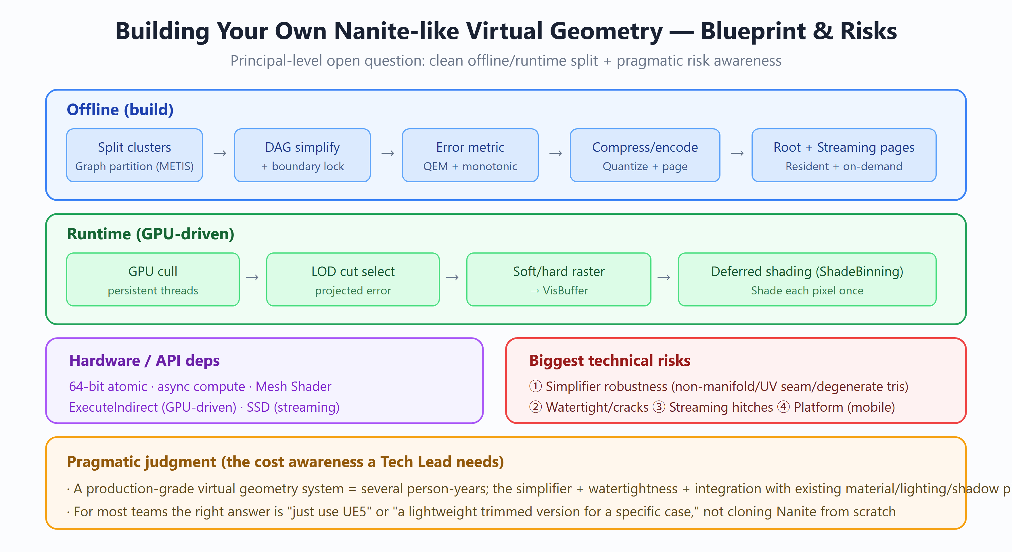
Model answer:
There’s no single right answer; this tests whether you can lay out the whole chain + identify the real hard parts + have a cost judgment. I’d cover four blocks: offline, runtime, dependencies, risks.
Offline (build):
raw mesh → cut clusters (graph partitioning, e.g. METIS) → DAG simplification (mesh simplifier + boundary locking for crack-free)
→ error metric (QEM, with monotonic parentError) → compressed quantized encoding + paging → Root pages (resident) + Streaming pages (on demand)
Runtime (GPU-driven):
GPU culling (persistent threads + work queue + ExecuteIndirect) → LOD cut selection (geometric error projected to screen pixels)
→ hybrid soft/hard rasterization → VisBuffer → deferred shading (ShadeBinning, shade each pixel once)
Hardware/API dependencies (without these, you can’t):
- 64-bit atomics (the heart of VisBuffer), async compute, Mesh Shaders, ExecuteIndirect (GPU-driven), SSD (streaming random reads).
The biggest technical risks (this is the real test):
- Mesh simplifier robustness — the most underestimated. It must robustly handle non-manifold geometry, UV seams, degenerate triangles, self-intersections… an unrobust simplifier cracks or explodes triangle counts on certain assets. This is one of the core assets Epic spent years polishing.
- Watertightness / cracks — fixed-point raster + boundary locking; any imprecision anywhere flickers across the screen.
- Streaming latency and hitches — page scheduling, camera-cut spikes (even Nanite needs HZB priming to mitigate).
- Integration with the existing pipeline — material system, lighting, shadows, translucency fallback all need adapting.
- Platform compatibility — mobile may lack 64-bit atomics / Mesh Shaders; the whole approach needs a fallback.
The pragmatic judgment (what a Tech Lead/Principal should have): a production-grade virtualized geometry system = multiple person-years of investment, with the simplifier + watertightness + pipeline integration being the real hard parts. For most teams the right answer is “use UE5 directly” or “build a lightweight, scenario-specific subset,” not cloning Nanite from scratch. Being able to state that cost judgment matters more than reciting the technical plan in full.
✅ Scoring rubric (by tier)
- 〔Pass〕 *”Two blocks, offline and runtime. Offline cuts the mesh into clusters, does simplification and LOD, compresses and stores; runtime culls, picks LOD, and rasterizes on the GPU. The biggest risk is getting mesh simplification wrong.”*
→ Why it scores: catches the two-stage skeleton (offline build + runtime pipeline) and pins the biggest risk on the mesh simplifier — right main line. Pass.
- 〔Good〕 *”Offline flow: cut clusters, can use graph partitioning like METIS; then a simplifier for DAG simplification with boundaries locked; error metric via QEM kept monotonic; finally compress and page into Root and Streaming pages. Runtime is GPU culling, LOD cut, hybrid soft/hard raster, VisBuffer, then deferred shading. Hardware-wise it depends on 64-bit atomics, async compute, Mesh Shaders, and SSD.”*
→ Why it scores: threads the full offline five steps (cut/DAG-simplify/error-metric/compress-page/Root+Streaming pages) and runtime chain, and names key mechanisms and hardware deps (METIS, QEM, boundary locking, hybrid raster). Knows why.
- 〔Strong〕 *”I’d rank the risks: first, mesh-simplifier robustness — non-manifold, UV seams, degenerate triangles are the most underestimated, and a broken simplifier kills the whole pipeline; second, watertightness and cracks — misaligned cluster boundaries after simplification leak light; third, streaming hitches — camera cuts spike; then pipeline integration and platform compatibility — without 64-bit atomics on mobile, the whole thing won’t run. Why lock boundaries during DAG simplification and keep the error metric monotonic — precisely to keep adjacent LODs from cracking and the cut from snapping.”*
→ Why it scores: not just listing risks but ranking them and explaining “why the simplifier is most underestimated,” and explaining the causality of boundary locking, QEM monotonicity → no cracks/no snapping — engineering dialectics and real prediction of failure modes.
- 〔Bonus〕 *”For runtime culling I’d use persistent threads + ExecuteIndirect to make the GPU self-driven; paging designed as resident Root pages + on-demand Streaming pages, with Root pages guaranteeing minimum visible quality. The error metric must be monotonic, or the LOD cut can’t select a consistent cross-section on the DAG and the surface breaks. Pragmatically, production-grade is multiple person-years, with UV seams and non-manifold handling eating most of it, and the right choice for most teams is to use UE5 rather than build their own.”*
→ Why it scores: gives implementation-level mechanisms (persistent threads + ExecuteIndirect GPU self-drive, resident Root pages for floor quality, the relation of monotonicity to DAG-cut consistency) and a pragmatic engineering judgment (person-year cost, most teams should use UE5) — depth plus grounded clarity.
⛔ Red flags (what’s wrong / why / what’s correct)
- “Just cut clusters by a spatial grid; how you cut doesn’t matter, it gets simplified later anyway.”
– What’s wrong: cluster-cut quality directly affects downstream boundary locking, error accumulation, and culling granularity; sloppy cuts cause too many boundaries and crack/error explosions during simplification.
– Correct: cut by connectivity/topology with graph partitioning (e.g. METIS) for cohesive clusters with minimal boundary, to support DAG simplification and crack-free LOD.
- “Just estimate the error metric with some number; monotonic or not doesn’t matter.”
– What’s wrong: a non-monotonic error metric means the LOD cut can’t select a consistent cross-section on the DAG, and adjacent LODs snap and break.
– Correct: the error metric must be monotonic (e.g. QEM keeping error monotonically increasing along the DAG), so runtime LOD cuts by error threshold give continuous, snap-free results.
- “This isn’t hard — a few people in a few months can write a paper-based version that ships.”
– What’s wrong: severely underestimates simplifier robustness (non-manifold/UV seams/degenerate triangles), watertightness, streaming hitches, platform compatibility — fail any one and it can’t ship.
– Correct: production-grade virtualized geometry is multiple person-years, with UV seams and non-manifold handling alone eating most of it; the pragmatic choice for most teams is to use UE5.
🕳️ Plausible-but-wrong traps (sound right, only half-understood)
- “QEM-based simplification is enough; QEM itself guarantees no cracks.” — The half-truth: QEM addresses the error metric and monotonicity, but doesn’t automatically guarantee inter-cluster watertightness; no-crack also needs explicitly locking cluster boundaries during DAG simplification (boundary vertices not collapsed). QEM and boundary locking are two things — saying only QEM is half-understood.
- “Runtime is just GPU culling and LOD selection, no different from traditional LOD, just moved to the GPU.” — The half-truth: traditional LOD is discrete whole-model switching with CPU decisions; this is cluster-level continuous LOD, with persistent threads + ExecuteIndirect making the GPU self-drive a cut on the DAG — granularity, decision location, and continuity all differ. Not a simple “moved to the GPU.”
- “Using METIS to cut clusters is for speed, graph partitioning is efficient.” — The half-truth: METIS isn’t used for its speed but to cut cohesive, minimal-boundary clusters by graph connectivity, serving downstream boundary-locked simplification and culling granularity; cut *quality* (few boundaries, high cohesion) is the goal, not speed.
🔍 Follow-up probes (the interviewer drills down)
- Why lock cluster boundaries during DAG simplification, and what if you don’t? → Without locking, adjacent clusters simplify independently and the shared-edge vertices get collapsed independently, so the two sides misalign and crack/leak light; locking keeps boundary vertices consistent during simplification, guaranteeing inter-cluster watertightness.
- What exactly does error-metric “monotonicity” solve at runtime? → It keeps error monotonic from fine to coarse along the DAG, so a runtime LOD cut by error threshold can select a consistent cross-section, and adjacent LODs join without snapping or breaking; non-monotonic risks selecting a self-contradictory cut causing cracks or flicker.
- Why separate Root and Streaming pages, and what does the Root page guarantee? → Root pages are resident, guaranteeing every mesh has a minimum visible quality always available, avoiding nothing-to-show before streaming arrives; Streaming pages stream high detail per camera/screen demand — the split balances memory and bandwidth between floor quality and on-demand detail.
- Why does this barely run on mobile — what’s missing? → Mainly 64-bit atomics (VisBuffer’s depth+ID atomic write depends on them); many mobile GPUs also lack mature async compute and Mesh Shader support, plus there’s no SSD-class streaming bandwidth — so the hardware dependencies don’t hold on mobile and it won’t run.
Probe prep: deeper questions on “how exactly does the mesh simplifier guarantee crack-free and monotonic error” lead to Q13.
Build / Shading at the Source Level (Q12–Q16)
<a name=”q12″></a>
Q12. What partitioning algorithm cuts clusters? Why not a spatial grid? Why is a cluster ~128 triangles?
Model answer:
When Nanite builds, it cuts the mesh into clusters using graph partitioning, not a spatial grid.
Concretely: build the triangles’ adjacency into a graph (triangles are nodes, shared edges are links), then partition that graph. The source uses the METIS library (FGraphPartitioner), with constraints MinPartitionSize≈124, Max=128 (ClusterDAG.cpp:132-174).
Why not a spatial grid: a simple spatial grid (e.g. dicing the bounding box into cells, a triangle joining whichever cell it falls in) severs surface connectivity — one continuous surface gets cut across different clusters by the grid lines, producing many fragmented cluster boundaries. Then during LOD simplification, all cross-cluster boundaries must be locked (see Q4/Q13), and with many fragmented boundaries there’s almost no interior left to simplify — LOD can’t climb.
Graph partitioning is different: it partitions by topological adjacency + spatial locality, making a cluster’s triangles both spatially close and topologically connected, with minimal cut edges between clusters. The source also uses Morton code to establish spatial-locality links (each element up to 5 neighbor links), grouping spatially close triangles preferentially. So each cluster is a “complete little surface patch,” with clean boundaries and an interior that simplifies well.
Why ~128 triangles per cluster: it’s a GPU-friendly granularity — matching wave / threadgroup sizes, and the basic batching unit for culling and rasterization (VisBuffer’s 7-bit triangle index encodes ≤128 exactly, see Q1). Too large coarsens culling granularity and wastes; too small raises management overhead and data redundancy.
A detail: cases of edges shared by multiple triangles must be sorted for determinism (ClusterDAG.cpp:72-101), or the build isn’t reproducible — important for repeatable asset baking.
✅ Scoring rubric (by tier)
- 〔Pass〕 *”Cluster cutting chops the mesh into chunks of about a hundred-some triangles each, not arbitrarily — by how faces are adjacent.”*
→ Why it scores: right direction, catches “cut by adjacency not space” and “~128,” but doesn’t say why.
- 〔Good〕 *”It builds triangle adjacency into a graph then partitions it, so each cluster is a small continuous surface patch with fairly clean boundaries; a spatial grid could put several disconnected patches in one cluster and fragment the boundaries.”*
→ Why it scores: knows why — explains graph partitioning preserves connectivity and spatial cutting severs surfaces, can distinguish the consequences of the two.
- 〔Strong〕 *”The key is downstream simplification. Cluster-boundary edges must be locked to align with neighbors during simplification; the more fragmented the boundary, the more locked edges, until a cluster is all locked boundary with no interior to simplify — LOD can’t climb. So you must cut by topological adjacency to keep boundaries short and few. 128 is GPU-friendly, aligning with wave/threadgroup, and VisBuffer reserves 7 bits for the triangle index, 2^7 = 128 exactly.”*
→ Why it scores: explains the downstream causal chain of “why boundaries can’t be fragmented” (boundary locking → no interior to simplify → LOD can’t climb), and attributes 128 to both GPU granularity and VisBuffer bit width — dialectical, not rote.
- 〔Bonus〕 *”It’s FGraphPartitioner using METIS-style graph partitioning, MinPartitionSize about 124, Max 128, code around ClusterDAG.cpp line 130-something. The graph also mixes in Morton code for spatial locality, not pure topology. Multi-triangle shared edges are sorted for determinism so baking is reproducible.”*
→ Why it scores: gives implementation-level evidence (FGraphPartitioner/METIS/MinPartitionSize≈124/ClusterDAG.cpp:132) and the Morton-locality and determinism-sorting details — has read the source, not just memorized points.
⛔ Red flags (what’s wrong / why / what’s correct)
- “Dice the model with a spatial octree/uniform grid, each block a cluster — simple and uniform.”
– What’s wrong: spatial cutting splits one continuous surface across clusters and stuffs disconnected faces into one, severing surface connectivity and fragmenting boundaries.
– Correct: build a graph from triangle adjacency and partition it; each cluster is a complete little surface with clean boundaries.
- “128 is just an empirical, off-the-cuff number; 256 or 64 would be fine.”
– What’s wrong: 128 isn’t arbitrary — it aligns with GPU wave/threadgroup granularity and is hard-bound to VisBuffer’s 7-bit triangle index (2^7 = 128).
– Correct: 128 is a deliberate, GPU-friendly choice echoing the VisBuffer bit width; changing it means changing the index encoding too.
- “Graph partitioning only needs topological adjacency; spatial position doesn’t matter.”
– What’s wrong: pure topology can cut spatially long, non-compact clusters, hurting bounding boxes and culling.
– Correct: partitioning mixes in Morton code for spatial locality — topological adjacency + spatial locality combined.
🕳️ Plausible-but-wrong traps (sound right, only half-understood)
- “Graph partitioning is to make each cluster’s triangle count uniform, to hit 128.” — The half-truth: count uniformity is a secondary scheduling concern; graph partitioning’s primary goal is preserving surface connectivity and keeping boundaries short and clean, serving downstream simplifiability — not hitting a number.
- “Clean boundaries are for faster rendering.” — The half-truth: the real payoff of clean boundaries is in the simplification stage (fewer locked edges → interior to simplify → LOD can climb), not render speed; pinning the payoff on rendering misreads the LOD build chain.
- “128 because a wave is 128 threads.” — The half-truth: wave width is 32/64; 128 is a threadgroup-magnitude match, and the real hard constraint is VisBuffer’s 7-bit triangle index. Reciting “wave=128” conflates granularity alignment with the bit-width constraint.
🔍 Follow-up probes (the interviewer drills down)
- In graph partitioning, what are the graph’s nodes and edges? → Nodes are triangles, edges are two triangles sharing a mesh edge (adjacency); edge weights can combine shared-edge length / normal difference, the goal being to minimize the cut edges, i.e. total cluster-boundary length.
- If cutting by adjacency, why also mix in Morton code? → Pure topology can cut spatially long clusters with loose bounding boxes and poor culling; Morton brings spatial locality so clusters are both connected and compact, aiding BVH and occlusion culling.
- Why is MinPartitionSize 124 and not just 128? → To leave slack, giving the partitioner freedom in the 124~128 range to find cleaner cuts; hard-pinning 128 forces more fragmented boundaries, and the upper bound 128 is the ceiling set by VisBuffer index bit width.
- Why does “sorting multi-triangle shared edges for determinism” matter for baking? → The same mesh must produce byte-identical cluster partitioning across machines / builds, or baking isn’t reproducible and incremental builds and caches all break; a stable edge sort removes the nondeterminism from hash-traversal order.
<a name=”q13″></a>
Q13. How is LOD error computed? How does simplification avoid cracks? Why must parent error ≥ child error?
Model answer:
This is a three-parter, and the three points interlock; I’ll cover them separately then show how they mesh.
① How error is computed — QEM (quadric error metric): simplification is done by FMeshSimplifier; Simplify(NumVerts, TargetNumTris, MaxErrorSqr) returns MaxErrorSqr (Cluster.cpp:549-743). That value is the worst-case squared distance from any point to the simplified mesh — a quantification of how much geometric detail simplification dropped. After sqrt and inverse-scaling back to the original coordinate system, it’s the cluster’s LODError. Attributes are weighted during simplification: normals 1.0, UVs by area, bone weights 0.
② Why no cracks — boundary locking: when simplifying a group, iterate edges with ExternalEdges[i]≠0 (shared with other clusters) and LockPosition() both endpoints, immovable during simplification (Cluster.cpp:660-675). So adjacent clusters simplify independently, but the shared-edge vertex positions stay vertex-aligned — no cracks. (Note: this is macro-level seamlessness; micro pixel-level watertightness comes from Q3’s fixed-point raster.)
③ Why monotonic — parentError ≥ childError: the source forces ParentLODError = max(ParentLODError, SimplifyError) (ClusterDAG.cpp:1070). The reason traces to runtime LOD selection: picking LOD is finding a “cut” on the DAG (Q5), judged by projecting error to screen pixels. If parent error < child error, that judgment self-contradicts — it might select both a parent and its child, causing geometric overlap or holes. Monotonicity guarantees “error grows toward the upper DAG,” so the cut selection is well-defined.
How the three mesh (the causal chain for full marks):
- QEM gives each cluster a geometric error → runtime projects it to screen pixels to pick LOD;
- boundary locking keeps same-level adjacent clusters from cracking;
- monotonicity keeps cross-level selection well-defined.
- Miss any one: inaccurate error → LOD flicker / no boundary lock → cracks / non-monotonic → overlap-holes.
✅ Scoring rubric (by tier)
- 〔Pass〕 *”Error is how much geometry differs before/after simplification, via QEM; no cracks because cluster-boundary vertices are locked; the parent’s error is surely bigger than the child’s because the parent is coarser.”*
→ Why it scores: all three conclusions right (QEM/boundary locking/parent≥child), catches the core mechanism names, but stops at “what” without “why it must be so.”
- 〔Good〕 *”Error is QEM’s worst-case squared distance, square-rooted and scaled back to the original coordinate system. No cracks: iterate boundary edges with nonzero ExternalEdges and lock both endpoints, so adjacent clusters simplify independently but the shared edge stays vertex-aligned. Parent error takes max(parent, this simplification’s error), guaranteeing monotonic non-decrease.”*
→ Why it scores: knows why, accurately describes all three mechanisms (MaxErrorSqr→sqrt inverse-scale, ExternalEdges-based locking, max for monotonicity), detailed.
- 〔Strong〕 *”The three interlock: QEM gives each cluster an error → runtime projects it to screen to pick LOD; locking keeps same-level neighbors from cracking; monotonicity keeps cross-level well-defined. Monotonicity is most crucial — runtime LOD selection is essentially finding a cut on the DAG, and if parent error is smaller than a child’s, the projection judgment self-contradicts and selects both parent and child, rendering geometric overlap or holes. So ParentLODError must be forced ≥ child.”*
→ Why it scores: explains how the three cooperate, especially pushing the harm of “parent < child” to the DAG-cut level (self-contradiction → both selected → overlap/holes) — dialectical understanding, not isolated memory.
- 〔Bonus〕 *”QEM is FMeshSimplifier::Simplify returning MaxErrorSqr, sqrt and inverse-scale around Cluster.cpp line 549. Attributes are weighted: normals 1.0, UVs by area, bone weights 0. Locking is LockPosition at Cluster.cpp 660. The monotonicity line is ClusterDAG.cpp:1070’s ParentLODError = max(ParentLODError, SimplifyError).”*
→ Why it scores: all implementation-level symbols hit (FMeshSimplifier::Simplify/MaxErrorSqr/Cluster.cpp:549/660/ClusterDAG.cpp:1070), plus the specific attribute weights — proves reading down to the code line.
⛔ Red flags (what’s wrong / why / what’s correct)
- “LOD error is the percentage of vertices removed — remove more, bigger error.”
– What’s wrong: vertex-removal count and geometric deviation aren’t the same; removing many vertices on a flat region barely changes geometry, removing one on a curved surface can deviate a lot.
– Correct: error is QEM’s worst-case squared distance from any point to the simplified mesh — measuring geometric shape deviation, not the topological removal count.
- “Adjacent clusters crack after simplification, so detect cracks at runtime and stitch/patch triangles.”
– What’s wrong: Nanite does no runtime stitching — that’s slow and unreliable.
– Correct: at build time, LockPosition freezes cluster-boundary-edge endpoints, so adjacent clusters simplify independently but the shared edge’s vertices are naturally aligned — no cracks at the source.
- “The parent error can just equal the sum (or average) of child errors.”
– What’s wrong: sum/average can’t guarantee monotonic non-decrease; once parent < child, runtime LOD projection self-contradicts and selects both, causing overlap or holes.
– Correct: parent error = max(parent’s accumulated error, this simplification’s error), using max to force monotonic increase.
🕳️ Plausible-but-wrong traps (sound right, only half-understood)
- “QEM computes the average distance from simplified vertices to the original mesh.” — The half-truth: Nanite uses MaxErrorSqr, the worst-case distance, not the average; averaging underestimates extreme deviation and fails to cut where it should during LOD selection — average and worst-case differ entirely in conservativeness.
- “Boundary locking just removes boundary vertices from simplification.” — The half-truth: it Locks the position so it can’t move/collapse — the vertex and edges remain, just immovable; removing boundary vertices would break alignment with neighbors and create cracks.
- “Parent error ≥ child error arises naturally from the simplification algorithm; no need to enforce it.” — The half-truth: adjacent clusters simplify independently, and a parent’s actual error in some pass can incidentally be smaller than a child’s; monotonicity doesn’t hold automatically and must be explicitly max-clamped, or DAG selection breaks.
🔍 Follow-up probes (the interviewer drills down)
- Why sqrt then inverse-scale the MaxErrorSqr QEM returns? → The internal computation is in a normalized/scaled space and is a squared quantity, while runtime needs a linear distance in the original world coordinate system to compare against the screen-projection threshold — so sqrt restores the dimension and the scale factor restores the scale (Cluster.cpp:549).
- Normals 1.0, UVs by area, bones 0 — why set them this way? → Normal deviation directly affects shading and must be penalized heavily; UV error is area-weighted to avoid small triangles dominating; bone weight is set 0 in the static simplification stage because skinning weights don’t participate in geometric error measurement, else they’d pollute the position error.
- How does ExternalEdges[i]≠0 decide whether an edge is a cluster boundary? → That count records how many of the cluster’s triangles share the edge / whether there’s a cross-cluster reference; nonzero means it’s an externally-exposed boundary edge (a neighbor cluster holds it too), so both endpoints get LockPosition (Cluster.cpp:660).
- How exactly does “finding a cut” on the DAG pick LOD at runtime? → Traverse the DAG top-down; for each cluster project its LODError to screen pixels, and if the error is below the threshold use that cluster (the cut is here), else descend to its children; monotonicity guarantees this cut is a well-defined antichain — the same surface region won’t select both a parent and a child.
<a name=”q14″></a>
Q14. Root Page vs. Streaming Page — what’s the difference? Why two kinds? Why is Transcode two passes?
Model answer:
Root vs. Streaming Page:
- Root Page: resident in GPU memory, 32KB, ≤64 clusters/page. Its role is to provide an immediately-renderable coarse geometry approximation — depending on no other page, so the asset can render a rough shape the moment it loads.
- Streaming Page: loaded on demand, 128KB, ≤512 clusters/page. Detail pages streamed in the background, referencing the Root page for incremental detail (
NaniteDefinitions.h:49).
Why two kinds: if everything streamed on demand, the first frame an asset enters view would have no geometry to render (still waiting on streaming) — a visible “pop” or hole. Resident Root pages solve this — render a coarse shape first, fill in detail as it streams. This is also a foundation of Nanite’s “something to render at any distance, smooth transitions.”
Why Transcode is two passes: pages stream in from disk in a compressed format (~50%), needing GPU decode (Transcode) into the runtime format. Two passes are fundamentally dependency decoupling:
- Pass 1 · Independent: handles data with no parent-page dependency — raw
FPackedClustercopy, Strip index decode, positions recovered from a ZigZag-compressed bitstream +WaveInclusivePrefixSum(NaniteTranscode.usf:401-574). - Pass 2 · ParentDependent: handles referenced vertices — decoded from the parent page/cluster (via
PageClusterMap,:576-667).
Why they must be split: a Root page must work independently (it has no parent data), so all its content decodes in the Independent pass; whereas a Streaming page’s referenced vertices must wait for the parent page. Splitting the two passes avoids GPU synchronization (no waiting on dependencies within one pass), with 64 threads handling one cluster.
Why GPU decode rather than a direct memcpy: disk stores the compressed format, the runtime format differs, and putting decode on the GPU saves disk/bus bandwidth (ship compressed, expand on the GPU).
✅ Scoring rubric (by tier)
- 〔Pass〕 *”Root pages are resident, smaller, fewer clusters, always there; Streaming pages stream on demand, bigger, more clusters. Two kinds so you don’t load everything at once.”*
→ Why it scores: right direction, catches “Root resident vs. Streaming on demand” and the size/cluster difference, but doesn’t clarify the two passes and the dependency.
- 〔Good〕 *”Root is about 32KB, ≤64 clusters, providing an immediately-renderable coarse geometry depending on no other page; Streaming is 128KB, ≤512 clusters, streamed in the background referencing Root for incremental detail. All-on-demand would pop on the first frame with no geometry; Root holds the line drawing the coarse version first, detail filled in after.”*
→ Why it scores: knows why, quantifies the two page specs (32KB/64 vs. 128KB/512), and explains the two kinds eliminate first-frame pop, catching Root’s self-containment.
- 〔Strong〕 *”Transcode’s two passes are fundamentally dependency decoupling. The Independent pass handles parent-independent data — raw copy, Strip index decode, ZigZag bitstream recovering positions with WaveInclusivePrefixSum; the ParentDependent pass handles referenced vertices, decoded from the parent page/cluster via PageClusterMap. Root must work independently so it all decodes in Independent, while Streaming’s referenced vertices wait for the parent. Splitting avoids GPU sync within one pass, 64 threads per cluster.”*
→ Why it scores: explains the essence of two-pass = dependency decoupling, clarifies “which data goes in which pass” and “why split” (avoid GPU sync), plus mechanism details like PageClusterMap and WaveInclusivePrefixSum.
- 〔Bonus〕 *”The spec constants are around NaniteDefinitions.h line 49. Transcode is GPU decode not memcpy — disk stores a compressed format (about 50%), the runtime format differs, and decoding on the GPU saves transfer bandwidth. ZigZag maps signed deltas to unsigned for bitstream packing, and the prefix sum is because positions are stored as deltas to be accumulated back.”*
→ Why it scores: gives the symbol (NaniteDefinitions.h:49), the compression ratio (~50%), the “GPU decode saves bandwidth” design motivation, and explains why ZigZag/prefix-sum exist — implementation-level evidence.
⛔ Red flags (what’s wrong / why / what’s correct)
- “Root and Streaming just differ in size, same function, both stream on demand.”
– What’s wrong: Root is resident and doesn’t stream, and must be self-contained (referencing no other page) — the prerequisite for first-frame immediate rendering, fundamentally different from Streaming’s on-demand reference semantics.
– Correct: Root resides on the GPU providing an immediately-renderable coarse approximation, Streaming streams on demand and references Root for increments — different roles, not just size.
- “Transcode just memcpys disk data to VRAM.”
– What’s wrong: disk stores a compressed, runtime-unusable format (bitstream/Strip/delta); a direct memcpy to VRAM can’t be read.
– Correct: Transcode is a GPU decode process (decompress, index decode, bitstream prefix-sum to recover positions); the compressed format is stored to save disk and transfer bandwidth.
- “Two passes are for parallelism, running together for speed.”
– What’s wrong: the two passes aren’t parallel but sequentially dependent — ParentDependent must wait for Independent (especially the parent page) to decode first.
– Correct: two passes are for dependency decoupling — separating dependency-free data from data needing the parent page, to avoid expensive GPU sync within one pass.
🕳️ Plausible-but-wrong traps (sound right, only half-understood)
- “The Root page is LOD0’s high-poly, loaded finest upfront.” — The half-truth: Root is precisely a coarse geometry approximation (the low-detail top of the LOD chain), to have something to draw immediately, with detail filled in by Streaming; treating Root as high-poly reverses the detail direction.
- “Independent vs. ParentDependent differ as one handles vertices, the other indices.” — The half-truth: the split is by “whether it depends on the parent page,” not vertex/index data type; Independent also decodes indices (Strip) and recovers positions, while ParentDependent handles cross-page referenced vertices.
- “Compressed storage is mainly to save disk space.” — The half-truth: saving disk is one side; more crucial is saving runtime PCIe/VRAM transfer bandwidth — ship compressed and decode on the GPU; bandwidth is Nanite streaming’s real bottleneck. Saying only “save disk” misses the “decode on GPU” design intent.
🔍 Follow-up probes (the interviewer drills down)
- Why must a Root page be “independent of other pages”? → Because it must render independently on the first frame, before any Streaming page arrives; once it references a not-yet-streamed page it can’t render immediately — self-containment is the hard prerequisite for an “immediately-renderable coarse approximation.”
- How exactly does the ParentDependent pass fetch “referenced vertices” from the parent? → Via PageClusterMap to locate the parent page/cluster; a child cluster stores only references/deltas to parent vertices, and on decode goes back to the parent page for the base vertices then adds the delta — hence it must wait for the parent to transcode first.
- Why ZigZag + prefix-sum for positions rather than storing floats directly? → Positions are stored as adjacent quantized deltas; deltas are small and signed, ZigZag maps signed to unsigned for variable-length bitstream packing, and at runtime WaveInclusivePrefixSum accumulates the deltas back to absolute positions — far higher compression than raw floats.
- How do 64 threads per cluster map to the data structure? → A cluster’s vertex/triangle count is in the hundreds, so 64 threads in one wave cover a cluster’s decode work, cooperating efficiently with wave intrinsics like in-wave prefix sums, and matching transcode’s per-cluster parallel partitioning.
<a name=”q24″></a>
Q24. How is Nanite’s position quantization precision auto-decided? Why 21 bits/axis? Why can’t wildly-different-scale geometry go into one asset?
Model answer:
This drills into the builder’s (NaniteBuilder) offline encoding, testing whether you’ve actually read the precision-decision code, not just “Nanite compresses geometry.”
First, the quantization structure. The whole mesh shares one uniform quantization grid: IntPosition = round(Position × 2^P), where P is the Position Precision and the step is 2^-P cm. Each cluster stores its own integer min-corner QuantizedPosStart and per-axis bit width QuantizedPosBits (the CeilLogTwo of the range), and vertices store only unsigned offsets from the min-corner — globally uniform precision, locally adaptive bit width — small clusters naturally use fewer bits.
How precision is auto-decided (default PositionPrecision = MIN_int32, i.e. Auto). The decision is in CalculateQuantizedPositionsUniformGrid (NaniteEncode.cpp:191-345), four steps:
- Density heuristic: iterate all leaf clusters (MipLevel == 0), take the mean log2 of bounding-box extents (AvgLogSize), then
PositionPrecision = 7 - round(AvgLogSize)(NaniteEncode.cpp:224). The intuition: clusters are a constant ~128 triangles, so smaller leaf clusters mean a denser mesh, deserving a finer step. A mesh whose average leaf cluster is 128 cm (2^7) gets P=0 (1 cm step); halve the leaf cluster size and P increments, halving the step. The source comment offers an equivalent reading: it’s “the average of what the clusters individually need.” - Auto-mode floor:
AUTO_MIN_PRECISION = 4, i.e. a 1/16 cm step (:231). The comment’s rationale is engineering-practical — lower precision contributes almost nothing to package size (~0.4% on a test project) yet invites trouble: a low-precision road/building frame fine in isolation will expose its quantization staircase once small props sit on it. Going lower needs explicit opt-in; auto mode won’t take the risk for you. - Global clamp: P is clamped to [-20, 43] (
NaniteDefinitions.h) — step from 2^20 cm (~10.5 km, planetary) to 2^-43 cm (subatomic). In practice Auto covers nearly every asset. - Auto-downgrade on overflow: with P fixed, check per cluster; if any axis’s integer range exceeds 2^21-1 after quantizing, halve the scale and decrement P, looping until all clusters encode (
NaniteEncode.cpp:250-271).
Why 21 bits/axis. The source comment is blunt: 21*3 = 63 < 64 (NaniteDefinitions.h) — the three quantized coordinates must fit a 64-bit budget, a hard constraint set by decoder efficiency.
Why wildly-different scales can’t share an asset. This is exactly step 4’s engineering implication: the downgrade is mesh-wide — one abnormally large cluster triggers a downgrade that drags down the entire mesh’s precision. So merging a large terrain and the tiny screws on it into one Nanite asset wrecks the screws’ precision under the terrain. This “build wildly-different-scale geometry as separate assets” guideline is derived directly from the precision-downgrade logic.
A consistent design philosophy: positions are quantized (not floats), normals are quantized too (octahedral, two components, up to 15 bits each), and tangents aren’t stored at all by default, derived at the pixel stage (see Q16). Because Nanite’s bottleneck is geometry data volume (memory/bandwidth/streaming), not pixel ALU, “quantize instead of storing floats, derive instead of storing” runs throughout.
✅ Scoring rubric (by tier)
- 〔Pass〕 *”Nanite quantizes vertex positions to integers; precision defaults to auto, set by mesh density — denser means higher precision.”*
→ Why it scores: catches three core conclusions — quantized storage + auto precision + tracks density. Right direction. Pass.
- 〔Good〕 *”It’s a uniform grid round(Position×2^P), P is precision, step 2^-P cm. Auto mode computes P=7-round(AvgLogSize) from the mean log2 of leaf-cluster sizes — smaller leaf = denser = higher precision. Each cluster stores its own bit width, small clusters using fewer bits.”*
→ Why it scores: can write the quantization formula and the auto-precision heuristic, and understands “leaf size as density proxy” and “per-cluster adaptive bit width.” Knows why.
- 〔Strong〕 *”Four steps: density heuristic sets P, AUTO_MIN_PRECISION=4 as a floor (lower precision saves little package size but exposes quantization staircases), clamp to [-20,43], then per-cluster check halving the scale and decrementing P if any axis exceeds 2^21-1. 21 bits because 21×3=63<64, three axes must fit a 64-bit budget. The most crucial engineering conclusion: the downgrade is mesh-wide, one huge-scale cluster drags the whole mesh’s precision down, so wildly-different-scale geometry can’t share an asset.”*
→ Why it scores: covers all four steps, gets the origin of 21 bits right, and derives from “overflow downgrade” the actionable guideline “wildly-different scales can’t share an asset” — from source detail to asset-organization advice, has read it and can use it.
- 〔Bonus〕 *”Code is around CalculateQuantizedPositionsUniformGrid line 191 in NaniteEncode.cpp, P=7-round(AvgLogSize) at line 224, AUTO_MIN_PRECISION=4 at 231, the downgrade loop at 250-271. Positions are ZigZag delta + WaveInclusivePrefixSum recovery (Q14), normals octahedral two components ≤15 bits each, tangents not stored by default and derived implicitly (Q16) — positions/normals/tangents all follow ‘quantize/derive instead of storing floats.'”*
→ Why it scores: gives the function name and specific line numbers, and threads position quantization into the unified compression philosophy of normal quantization and tangent derivation — proves reading down to the code line, systematically.
⛔ Red flags (what’s wrong / why / what’s correct)
- “Nanite still stores vertex positions as floats, just compressed.”
– What’s wrong: positions are quantized to integers (round(Position×2^P)), not compressed floats; each cluster stores an integer min-corner + per-axis bit width + unsigned offsets.
– Correct: integer encoding on a uniform grid, precision set by P, recovered to approximate float positions at runtime.
- “Precision must be set manually by the user; without it, a fixed default is used.”
– What’s wrong: the default is Auto (MIN_int32); the engine computes P automatically from leaf-cluster density, not a fixed constant; manual is needed only in a few cases like seam-critical pieces / extreme-scale objects.
– Correct: Auto runs the four-step density-heuristic + floor + clamp + downgrade automatically; the vast majority of assets need no manual setting.
- “Merging a large terrain and the small props on it into one Nanite asset is fine, since per-cluster bit width adapts.”
– What’s wrong: bit width is per-cluster adaptive, but P’s “overflow downgrade” is mesh-wide — a huge-scale terrain cluster triggers a downgrade that drags the whole asset’s (including the props’) precision down.
– Correct: build wildly-different-scale geometry as separate assets to avoid large-scale clusters wrecking small props’ precision.
🕳️ Plausible-but-wrong traps (sound right, only half-understood)
- “Precision tracks triangle count — more triangles, higher precision.” — The half-truth: the heuristic looks at leaf-cluster bounding-box size (mean log2), not triangle count. Because a leaf cluster is a constant ~128 triangles, cluster size is what reflects local density; saying “more triangles, finer” misses the “size = density proxy” layer.
- “21 bits is some kind of precision optimum.” — The half-truth: 21 isn’t a precision optimum, it’s the 64-bit budget divided across three axes (21×3=63<64). It’s a decoder-side capacity constraint, not “21 bits of precision is just enough.”
- “The auto-precision floor of 4 is because any lower and quality collapses.” — The half-truth: the floor of 4 is because lower precision saves little package size (~0.4%) yet exposes quantization staircases in multi-object scenes — a benefit/risk trade-off, not simply “any lower and it breaks.”
🔍 Follow-up probes (the interviewer drills down)
- What does the 7 in auto-precision’s
7 - round(AvgLogSize)mean? → It makes a mesh whose average leaf cluster is 2^7=128 cm get P=0 (1 cm step) as the anchor point; halve the leaf cluster size and AvgLogSize drops by 1, P increments and the step halves — so 7 is the constant anchoring “128 cm leaf ↔ 1 cm step.” - Why use leaf-cluster size rather than triangle count directly as the density metric? → A leaf cluster is a constant ~128 triangles, so its bounding-box size directly reflects “how much space this many triangles occupy,” i.e. local density; size expresses “how fine a quantization step is needed” more directly than count.
- Why must the overflow downgrade affect the whole mesh and not just the large cluster? → Because P is the mesh-wide quantization exponent (the premise of the uniform grid); giving one cluster a different P would break the uniform grid, so an un-fitting cluster forces a mesh-wide P drop — the cost being that small props suffer at wildly-different scales, which in turn requires avoiding mixed scales at the asset level.
- How does this precision relate to Q14’s Transcode compression? → Quantization (this question: setting P and bit width, storing integer offsets) is the first encoding layer, determining geometry’s numeric precision; Transcode (Q14) further ZigZag-deltas and bitstream-packs the quantized data and decodes it on the GPU — the second layer of lossless compression and recovery. How many bits precision uses is the quantization layer’s concern; how to transfer/decode those bits efficiently is Transcode’s.
<a name=”q25″></a>
Q25. Why does cluster graph partitioning use METIS rather than libraries like meshoptimizer / nvcluster? Do intra-cluster vertices use indirect indices?
Model answer:
These are two questions drilling into the NaniteBuilder implementation, distinguishing “read the source” from “memorized the intro.” Answered separately.
① Why METIS — first correct a common misconception: METIS isn’t all of the “split triangles into clusters” step, it’s just called to solve a math subproblem.
Look at FGraphPartitioner‘s (GraphPartitioner.cpp) real structure: the outer layer is Epic’s own recursive bisection framework — PartitionStrict → RecursiveBisectGraph → BisectGraph, where each call has METIS do a single 2-way min-cut bisection (METIS_PartGraphRecursive, NumParts=2, :172), after which Epic itself checks “are both sides ≤MaxPartitionSize (128)” and recurses if not (:235-280). METIS does not do a one-shot k-way partition (that METIS_PartGraphKway path :56 is used only on a small graph already ≤128).
In other words, METIS here is just a building block providing “given a graph, do one balanced min-cut bisection.” The three things that actually determine Nanite cluster quality are wrapped by Epic around METIS:
- A hard ≤128 cap: METIS itself only guarantees “roughly balanced” (via the
METIS_OPTION_UFACTORtolerance,:165), not that each block is strictly ≤128; the dead cap is enforced by the outer recursive framework. - Determinism: after multithreaded bisection,
PartitionStrictforcesRanges.Sort()(:342, comment// Force a deterministic order) — guaranteeing byte-identical builds for the same mesh, reproducible baking. - Morton locality links:
BuildLocalityLinksadds edges between elements spatially close but topologically disconnected (up to 5 per element,MaxLinksPerElement=5), making clusters both topologically connected and spatially compact.
So why not meshoptimizer / nvcluster:
- meshoptimizer’s
buildMeshletssolves meshlet partitioning — its goals are vertex-reuse rate + cone-cull friendliness (for mesh shaders), and it does not target “global min-cut + serving later DAG simplification.” Nanite’s clusters need short boundaries (later LockPosition-locked, leaving simplifiable interior, see Q4/Q13), a different demand from meshlets, so using meshopt would mean rewriting an adaptation layer. - nvcluster (NVIDIA’s cluster builder) is closer to Nanite’s clusters, but it’s a 2023+ thing (with RTX Mega Geometry), while Nanite’s METIS code was set in 2021 (UE5 EA) — Nanite far predates nvcluster, so there was no “could-have-chosen nvcluster but chose METIS.” (This is a timeline inference; the source can only prove “it uses METIS,” not “it evaluated nvcluster.”)
In one line: METIS isn’t “picked” from a pile of cluster libraries, it’s a mature industrial implementation of the “do one min-cut graph bisection” atomic operation; the capacity cap, determinism, and locality — Nanite’s particular demands — are all wrapped by Epic.
② Vertex replication — not a naive indirect index, but a triangle-strip + Ref/New-vertex variable-length encoding.
A naive indirect index is “3 absolute vertex indices per triangle (32-bit each),” with shared-edge vertices re-referenced and the index data large. Nanite doesn’t do this (NaniteEncodeTriStrip.cpp:141 UnpackTriangleIndices, the runtime transcode shader running the same logic):
- Triangles are striped, each vertex being either a New vertex (new, implicitly numbered in order,
NextVertex++,:178, costing no index bits) or a Ref vertex (back-referencing an already-seen vertex, storing a 5-bit relative offsetBaseVertex - (IndexData & 31u),:178); FStripDesc.NumPrevRefVerticesBeforeDwords/NumPrevNewVerticesBeforeDwords(Cluster.h:195-196) are per-dword prefix counts, combined with the bitmaskCountBitsto compute on the fly the current triangle vertex’s absolute position in the compact array.
There’s another layer at build time: FVertexArray::FindOrAddHash (Cluster.h:103) does intra-cluster vertex hash dedup, storing duplicate vertices once.
Why this design: advancing the strip by one triangle usually adds just 1 New vertex, the other 2 back-referencing priors, so most vertices cost 0 index bits, only reused vertices cost 5 bits — far cheaper than “3 32-bit absolute indices per triangle.” The 5-bit limit (back-ref up to 32 vertices) matches the strip’s locality exactly. This is consistent with Nanite’s global “compress where you can” philosophy (echoing Q14’s ZigZag/prefix-sum, Q24’s quantization, Q16’s tangent derivation).
✅ Scoring rubric (by tier)
- 〔Pass〕 *”Graph partitioning uses the METIS library; vertices aren’t stored as absolute indices per triangle, but reuse shared vertices via strips.”*
→ Why it scores: right direction, knows METIS is the graph-partitioning library and vertices use strip reuse not naive indices. Pass.
- 〔Good〕 *”METIS only does the min-cut graph bisection, and around it Epic’s own recursive framework controls cutting to ≤128 and adds a deterministic sort. Vertices are strip-encoded, split into New and Ref, where Ref stores a relative back-offset to a prior vertex, not an absolute index.”*
→ Why it scores: states METIS as just the bisection block with the outer framework controlling capacity + determinism, and clarifies the strip’s New/Ref split and “relative back-offset.” Knows why.
- 〔Strong〕 *”In GraphPartitioner, METIS only does a single 2-way bisection (PartGraphRecursive, NumParts=2), Epic’s RecursiveBisectGraph recurses to ≤128, and after multithreading Ranges.Sort guarantees determinism with Morton locality links for spatial locality — all three wrapped around METIS. Not meshopt because its buildMeshlets solves meshlets (vertex reuse + cone cull), not the min-cut serving later DAG simplification; nvcluster is 2023+, later than Nanite. Vertex encoding is strip+Ref/New, New vertices 0 index bits, Ref vertices a 5-bit relative back-offset, located by prefix counts, most vertices costing no index bits.”*
→ Why it scores: explains METIS’s “block vs framework” layering thoroughly (bisection granularity + recursion + determinism + locality), the right reasons for not choosing meshopt/nvcluster (different goal / timeline), and the complete strip+5-bit back-ref vertex-encoding mechanism — implementation-level understanding of having read NaniteBuilder.
- 〔Bonus〕 *”Concrete symbols: bisection at METIS_PartGraphRecursive (GraphPartitioner.cpp:172), small graphs take PartGraphKway (:56), UFACTOR loosened to 200 at high levels and tightened to 1 near cluster size (:165); determinism is :342’s Ranges.Sort, comment ‘Force a deterministic order.’ Vertex UnpackTriangleIndices at NaniteEncodeTriStrip.cpp:141, the 5-bit back-ref is BaseVertex-(IndexData&31), prefix-count fields in FStripDesc (Cluster.h:195); build-time dedup is FVertexArray::FindOrAddHash (Cluster.h:103). Runtime GPU transcode uses the same unpack logic.”*
→ Why it scores: function names + line numbers + constants all hit (PartGraphRecursive/Kway, UFACTOR 200↔1, Ranges.Sort, UnpackTriangleIndices, FStripDesc, FindOrAddHash), and notes runtime and build-time share the unpack logic — code-line-level evidence.
⛔ Red flags (what’s wrong / why / what’s correct)
- “Nanite uses METIS to do the whole cluster partitioning in one shot.”
– What’s wrong: on the main path METIS only does a single 2-way bisection; Epic’s RecursiveBisectGraph framework calls it recursively and itself enforces the ≤128 capacity cap and determinism; the k-way path is used only on small graphs.
– Correct: METIS is a building block (one min-cut bisection), and the capacity/determinism/locality three layers are wrapped by Epic.
- “Vertex replication is just three vertex indices per triangle (indirect index).”
– What’s wrong: that’s the naive scheme with large index data. Nanite uses strip + Ref/New, New vertices costing no index bits, Ref vertices storing only a 5-bit relative back-offset.
– Correct: striped variable-length encoding, most vertices implicitly ordered, only reused vertices costing 5 bits — far cheaper than absolute indices.
- “meshopt / nvcluster are better, Nanite didn’t use them because it didn’t keep up.”
– What’s wrong: meshopt’s meshlet partitioning has a different goal (vertex reuse + cone cull, not min-cut + DAG simplify); nvcluster is 2023+, later than Nanite’s METIS scheme — not “didn’t keep up.”
– Correct: METIS provides exactly the “min-cut graph bisection” atomic operation Nanite needs, with the rest implemented by Epic; on the timeline nvcluster also postdates this code.
🕳️ Plausible-but-wrong traps (sound right, only half-understood)
- “METIS is used because graph-partitioning algorithms are fast.” — The half-truth: not for speed. METIS provides the “min-cut bisection” *quality* operator, and Nanite needs clusters with short boundaries, cohesion, and later simplifiability; speed isn’t the core demand (high-level bisection even deliberately loosens UFACTOR, low-level tightens it).
- “Strip vertex reuse and the raster-stage wave vertex dedup are the same thing.” — The half-truth: two different layers. strip+Ref/New is build/encode-time index compression (saving storage/bandwidth); the raster stage’s
WaveActiveMinvertex dedup (mentioned in Q2) is runtime, making each unique vertex transform once (saving ALU) — different source and purpose. - “A 5-bit back-offset means a cluster has at most 32 vertices.” — The half-truth: 5 bits limits how far back a reference can reach (the prior 32 decoded vertices), not the cluster’s total vertex count; total vertex count is set by the vertex scale of 128 triangles, with strip order ensuring vertices to back-reference are within the last 32.
🔍 Follow-up probes (the interviewer drills down)
- How many ways does METIS partition in Nanite? → On the main path
PartGraphRecursivedoes only 2-way each time (NumParts=2), relying on Epic’sRecursiveBisectGraphto recursively bisect until all blocks are ≤128; only a small graph already ≤MaxPartitionSize takes the one-shotPartGraphKway. - Since METIS guarantees balance, why does the outer framework still enforce 128? → METIS’s
UFACTORis just a “load-imbalance tolerance,” giving rough balance not a hard cap; Nanite needs each cluster strictly ≤128 (the VisBuffer 7-bit index hard constraint), so the outer recursion must cut until all are ≤128. - A New vertex stores no index — how does decode know its number? → New vertices are implicitly numbered by appearance order, and decode uses the prefix count
NumPrevNewVerticesBeforeDwords+CountBitswithin the current dword to compute “how many New vertices precede this,” and the next New vertex is that number — so it needn’t be stored explicitly. - Why is the back-offset 5 bits and not more? → The strip’s locality guarantees the shared vertex to back-reference is almost always within the last 32 decoded vertices, and a 5-bit (0~31) relative back-offset covers it; more would be wasted. This is the co-design of strip order and encoding bit width.
<a name=”q15″></a>
Q15. How does Nanite shade each pixel exactly once, which traditional deferred can’t? What do ShadeBinning’s three passes do?
Model answer:
First, the fundamental difference from traditional deferred shading — the crux of this question, often confused.
Traditional deferred: the geometry pass runs the material shader and writes the GBuffer. The problem is this step shades occluded fragments too (they write the GBuffer first, get overwritten later) — overdraw exists; and cost is tied to the triangle × material PSO combination.
Nanite: the raster stage shades nothing, writing only VisBuffer64 (Q1). Shading happens only after all geometry is written and each pixel’s unique visible triangle is settled. So occluded pixels never enter material shading — zero overdraw shading waste.
ShadeBinning’s three stages (NaniteShadeBinning.usf):
- COUNT: each thread reads the VisBuffer + ShadingMask, extracts each pixel’s ShadingBin (which material), and uses
WaveActiveCountBitsto tally how many pixels each material bin covers. - RESERVE: per bin, allocate a pixel storage range from the global allocator.
bNoDerivativeOpsmaterials allocate per pixel, others per quad (2 pixels). Also generate the indirect dispatch arguments. - SCATTER: re-traverse the screen, compute each pixel’s exact write offset, and scatter the pixel into each bin’s data region (encoding
CoarsePixelTopLeft, VRSShift, WriteMask).
Result: each material needs only one compute shader, dispatched over only the visible pixels it actually covers: DispatchThreadCount = DivideAndRoundUp(BinPixelCount, GROUP_SIZE). So shading cost = screen pixels × a constant, fully decoupled from the scene’s product of triangle count and material variety. This is one reason Nanite can render “trillion triangles” in real time (however much geometry, each pixel is shaded once).
New in 5.7: Shader Bundle aggregates multi-material dispatches into a single GPU command buffer (lowering CPU submission overhead); Work Graph (SF_WorkGraphComputeNode) lets the GPU dynamically generate indirect tasks. But the three-stage algorithm itself is the 2021 original.
✅ Scoring rubric (by tier)
- 〔Pass〕 *”Nanite doesn’t shade during rasterization, just writes a visibility buffer; once each pixel’s final triangle is settled it shades, so each pixel is shaded once. Traditional deferred writes materials into the GBuffer in the geometry pass, shading occluded ones too.”*
→ Why it scores: right direction, catches the two core contrasts “visibility first, then shading” and “traditional deferred shades too early causing overdraw,” but doesn’t expand ShadeBinning’s three passes.
- 〔Good〕 *”Traditional deferred runs the material shader writing the GBuffer in the geometry pass, shading occluded fragments too, with cost being triangle×material PSO switches. Nanite’s raster writes only VisBuffer64 without shading, shades after all geometry is settled, occluded pixels never enter shading, so shading cost is decoupled from geometry, roughly screen pixels × a constant.”*
→ Why it scores: knows why, clarifies traditional deferred’s cost structure (triangle×material PSO) and Nanite’s “cost decoupled from geometry,” with VisBuffer64 landing accurately.
- 〔Strong〕 *”The key is ShadeBinning’s three stages. COUNT: read VisBuffer and ShadingMask to get each pixel’s ShadingBin, tally pixels per material bin with WaveActiveCountBits; RESERVE: allocate a pixel storage range per bin, per pixel or per quad by bNoDerivativeOps, and generate indirect dispatch arguments; SCATTER: compute each pixel’s exact write offset and scatter it in. Finally each material is one compute shader dispatched over only the visible pixels it covers — that’s why shading and geometry fully decouple.”*
→ Why it scores: explains what each of the three passes does and why it’s needed (count → allocate ranges → scatter), and points out key branches like bNoDerivativeOps, indirect dispatch — mechanism-level thoroughness.
- 〔Bonus〕 *”In detail, RESERVE’s bNoDerivativeOps decides per-pixel vs. per-2×2-quad granularity (derivatives require the quad). SCATTER’s write offsets handle VRS/coarse-shading cases like CoarsePixelTopLeft and VRSShift. 5.7 also adds Shader Bundle aggregating multi-material dispatches, and Work Graph, node type SF_WorkGraphComputeNode.”*
→ Why it scores: gives implementation-level symbols (bNoDerivativeOps/CoarsePixelTopLeft/VRSShift/SF_WorkGraphComputeNode) and 5.7 new features, proving it tracked the latest code and design evolution.
⛔ Red flags (what’s wrong / why / what’s correct)
- “Nanite shades each pixel once via Early-Z / a depth prepass culling occluded pixels.”
– What’s wrong: Early-Z only reduces some overdraw, still shading while rasterizing in the geometry pass, and the same pixel can still be shaded multiple times depending on draw order.
– Correct: Nanite fully defers shading until the VisBuffer is settled, then dispatches shading once per screen pixel by the visibility result — a different thing from a depth prepass.
- “ShadeBinning sorts triangles by material then batch-draws them.”
– What’s wrong: the binning target is screen pixels, not triangles, and it’s a compute dispatch, not raster drawing.
– Correct: ShadeBinning classifies pixels by each pixel’s ShadingBin (material), then uses a compute shader per material to shade only the visible pixels it covers.
- “Traditional deferred also shades once, so Nanite is no different in essence.”
– What’s wrong: traditional deferred’s geometry pass runs the material shader on occluded fragments too writing the GBuffer (overdraw exists), with cost ballooning with triangle and material count.
– Correct: Nanite’s raster stage shades nothing, shading strictly on visible pixels only, cost decoupled from geometric complexity — the essential difference.
🕳️ Plausible-but-wrong traps (sound right, only half-understood)
- “VisBuffer stores color, used directly for display afterward.” — The half-truth: VisBuffer64 stores visibility info (cluster ID + triangle ID, etc.), not color; color is computed afterward by ShadeBinning looking up the material from that ID — treating it as a color buffer misreads “writes only visibility, no shading.”
- “The three passes are COUNT counts pixels, RESERVE reserves memory, SCATTER writes color, order doesn’t matter.” — The half-truth: order is a hard dependency — you must COUNT per-bin pixels first to RESERVE contiguous ranges and indirect args, then SCATTER offsets; scramble the order and offsets can’t be computed.
- “Per-quad processing is for MSAA anti-aliasing.” — The half-truth: per-2×2-quad is to compute screen-space derivatives (ddx/ddy for mip/anisotropy), decided by bNoDerivativeOps; a different thing from MSAA, and materials needing no derivatives can degrade to per-pixel for savings.
🔍 Follow-up probes (the interviewer drills down)
- What exactly is encoded in VisBuffer64’s 64 bits? → Mainly the visible triangle’s identity — cluster/instance ID plus the in-cluster triangle index (those 7 bits) and depth; the shading stage uses it to look up the specific triangle and material, then recompute attributes — none of which shades at the raster stage.
- Why does COUNT count per-bin pixels first — can’t you shade while traversing? → To allocate a contiguous pixel storage per material bin and the indirect dispatch thread count, you must know the total first; shading-while-traversing reverts to a no-batch, no-precise-dispatch state and loses the “one compute per material” structure.
- bNoDerivativeOps true vs. false — how does dispatch granularity differ, and why? → True means the material needs no screen derivatives and can be scheduled per single pixel for savings; false needs ddx/ddy and must be per-2×2-quad to keep derivatives computable, filling the quad even if some pixels are invisible.
- What bottleneck in the three passes do 5.7’s Shader Bundle / Work Graph solve? → They solve the scheduling overhead and CPU/GPU round-trips of many small dispatches when material count is high — Shader Bundle aggregates multi-material dispatches into one, and Work Graph (SF_WorkGraphComputeNode) lets the GPU data-drive the expansion of shading work itself, reducing indirect readback and submission counts.
<a name=”q16″></a>
Q16. Without storing per-vertex tangents, how do you handle normal maps when needed? Costs and limits?
Model answer:
Nanite by default doesn’t store per-vertex tangents; when tangents (normal maps) are needed, it derives them implicitly at the pixel-shading stage from triangle vertex positions + UVs.
The mechanism (DecodeImplicitTangents, NaniteAttributeDecode.ush:610):
Perp2 = cross(N, edgeB)
Perp1 = cross(edgeA, N)
TangentX = normalize(Perp2*dUV1.x + Perp1*dUV2.x)
This is Christian Schüler’s screen-space derivation — using the normal N, two edges, and UV gradients to compute the tangent X on the fly. So normal maps work as usual, the tangent just being computed rather than looked up.
Why this design — the trade-off:
- What’s saved: Nanite assets have extreme geometric density, and per-vertex tangents cost real memory (one tangent vector per vertex). Dropping them significantly reduces geometry data volume.
- The cost: a bit more per-pixel compute; and implicit derivation handles mirrored UVs / UV seams less accurately than stored tangents (artifacts possible at seams).
- The fallback: it also supports optional stored tangents (
cluster.bHasTangents, angle + sign encoding), enableable for quality-sensitive assets.
The consistent design philosophy behind it: Nanite generally “compresses/derives rather than stores raw” for high-density geometry — normals are also quantized-and-compressed (2*NormalPrecision bits, recovered by UnpackNormal). Because Nanite’s bottleneck is geometry data volume (memory/bandwidth/streaming), not pixel ALU, trading compute for memory pays off.
✅ Scoring rubric (by tier)
- 〔Pass〕 *”Nanite doesn’t store per-vertex tangents, but normal maps still work — it computes tangents on the fly during shading from the triangle’s positions and UVs. The cost is a bit more per-pixel compute.”*
→ Why it scores: right direction, catches the two cores “doesn’t store tangents but derives from position+UV at runtime, normal maps still usable” and “cost on the pixel side,” but doesn’t give the derivation method and precision limits.
- 〔Good〕 *”Tangents are derived implicitly at the pixel-shading stage from triangle vertex positions and UVs: cross-product combinations of adjacent edges and UV gradients, TangentX roughly Perp2×dUV1.x plus Perp1×dUV2.x normalized, where Perp is the cross of the normal and an edge. This saves per-vertex tangent memory, significant for high-density geometry, at the cost of more per-pixel compute and less accuracy at mirrored UVs and UV seams than stored tangents.”*
→ Why it scores: knows why, writes the derivation formula shape (Perp cross-product + UV-gradient weighting) and the clear cost (memory saved vs. pixel ALU + seam precision) — the trade-off well covered.
- 〔Strong〕 *”This is Christian Schüler’s screen-space tangent derivation, in NaniteAttributeDecode.ush as DecodeImplicitTangents. It’s consistent with Nanite’s whole philosophy — geometry data volume is the bottleneck, pixel ALU isn’t, so it would rather compute more per pixel to drop per-vertex attributes. Likewise normals are quantized-and-compressed, about 2×NormalPrecision bits, decoded by UnpackNormal during shading. Not blindly saving — the fallback is cluster.bHasTangents optional explicit tangents (angle + sign encoding), enableable for mirrored-UV/seam-precision-sensitive assets.”*
→ Why it scores: explains the unified design philosophy of “why this trade” (geometry volume is the bottleneck, ALU isn’t), and folds normal quantization and the optional explicit-tangent fallback into the same logic — dialectical and complete.
- 〔Bonus〕 *”Implementation is DecodeImplicitTangents, around line 610 of NaniteAttributeDecode.ush. Normal compression is 2×NormalPrecision bits with UnpackNormal. The fallback field is cluster.bHasTangents, and explicit tangents use angle + sign encoding rather than storing the full 3D vector, compressing further.”*
→ Why it scores: complete implementation-level symbols (DecodeImplicitTangents/NaniteAttributeDecode.ush:610/cluster.bHasTangents/2×NormalPrecision/UnpackNormal), and notes explicit tangents also use angle+sign compression rather than a raw vector — code-level evidence.
⛔ Red flags (what’s wrong / why / what’s correct)
- “No stored tangents means no normal maps, so Nanite meshes can’t use normal maps.”
– What’s wrong: missing tangents doesn’t mean unrecoverable; Nanite derives the tangent basis implicitly from position+UV at the pixel stage, and normal maps work as usual.
– Correct: normal maps fully work, tangents derived at runtime by DecodeImplicitTangents, only with a different precision/cost trade-off.
- “Tangents are computed in the vertex stage (VS) then interpolated to pixels.”
– What’s wrong: Nanite has no traditional VS-interpolated-tangent path; derivation happens at the pixel-shading stage, based on that pixel’s triangle’s positions and UV gradients.
– Correct: tangents are derived on the fly during pixel shading by DecodeImplicitTangents, not computed at vertices and interpolated down.
- “Implicitly-derived tangents have exactly the same precision as stored ones — pure win.”
– What’s wrong: at discontinuities like mirrored UVs and UV seams, screen-space derivation deviates from the true tangent basis, less accurate than stored.
– Correct: good enough and memory-saving in most cases, but precision drops at seams/mirrors, hence keeping cluster.bHasTangents optional explicit storage as a fallback.
🕳️ Plausible-but-wrong traps (sound right, only half-understood)
- “Use ddx/ddy on UVs for screen derivatives to derive tangents.” — The half-truth: Nanite’s derivation uses triangle vertex positions and UV gradients (edges and dUV) in cross-product combinations (Schüler’s method), not the pixel quad’s ddx/ddy screen derivatives; different sources, and conflating them suggests tangents depend on quad derivatives.
- “The memory saving is mainly on normal-map sampling cost.” — The half-truth: the saving is on per-vertex tangent attribute storage/bandwidth, unrelated to normal-map sampling cost; normal maps still sample, only the tangent basis is computed on the fly — pinning the gain on texture sampling misses where it’s saved.
- “Normals are also implicitly derived, not stored like tangents.” — The half-truth: normals are explicitly quantized-and-compressed (about 2×NormalPrecision bits, UnpackNormal decode), not derived; only tangents are implicitly derived. Treating both normals and tangents as derived conflates “compressed storage” with “runtime derivation,” two different means.
🔍 Follow-up probes (the interviewer drills down)
- How exactly do Perp1/Perp2 in DecodeImplicitTangents arise, and why cross products? → Perp = cross(N, edge), i.e. crossing the normal with a triangle edge yields a basis vector perpendicular to the normal and in the tangent-plane direction; then weight-combine with the two edges’ UV increments (dUV1/dUV2) to align the tangent direction to UV’s U direction, finally normalizing (NaniteAttributeDecode.ush:610).
- Why do implicit tangents go wrong at mirrored UVs? → Mirrored UVs flip the chirality (sign) of the UV gradient, so the derived tangent direction/bitangent sign is discontinuous across the mirror seam, and the normal-map-decoded bump direction reverses; explicit storage can express it precisely with a sign bit, while derivation errs at the seam.
- How are normals’ “2×NormalPrecision bits” encoded, and why 2×? → A unit normal can be represented by two components (e.g. octahedral mapping’s two coordinates), each NormalPrecision bits, totaling 2×NormalPrecision, recovered to a 3D unit vector by UnpackNormal during shading — far cheaper than three raw floats.
- Given the cluster.bHasTangents fallback, why not enable explicit tangents by default? → Default derivation is to save memory (geometry volume is the bottleneck); enabling explicit tangents everywhere adds per-vertex tangent storage/bandwidth back, contradicting Nanite’s compression philosophy; enable it only on mirrored-UV/seam-precision-sensitive assets — pay-as-needed, not one-size-fits-all.
5.7 New Features + Architecture Finale (Q17–Q21)
<a name=”q17″></a>
Q17. How does Nanite Foliage handle dense vegetation’s sub-pixel triangles? The Voxel/Brick data structure + distance-driven LOD? Why does the voxel path not support WPO?

Model answer:
Dense vegetation (grass, leaves) is the classic sub-pixel triangle + severe overdraw scenario. Nanite Foliage (5.7)’s approach: when triangles shrink to sub-pixel, switch to near-pixel-sized voxels to represent them.
Voxel / Brick data structure (FBrick, NaniteDataDecode.ush:137):
ReverseBrickBits : uint2   // 64-bit bitmap = 4×4×4 = 64 voxels
StartPos / BrickMax : int3
VertOffset : uint
BoneIndex : uint           // new in 5.7, for voxel skinning
A Brick is 4×4×4 = 64 voxels, with a 64-bit bitmap marking which voxels exist. Two nested voxel-tree levels (VOXEL_NUM_LEVELS=2), PrefixSum64 doing a prefix sum over the bitmap to compute voxel indices. Each voxel stores a normal distribution (not a single normal), so lighting stays sane even as voxels and leaf volume is preserved.
Distance-driven LOD (AutoVoxel.usf:16):
Level = floor(log2(Distance * DistanceFactor / VoxelSize))
VoxelPos = floor(VoxelPos / 2^Level)
The farther, the larger Level and the larger voxels; up close, triangles or small voxels. So a distant tree automatically becomes a sanely-shaded blob of voxels, without rasterizing thousands of sub-pixel triangles.
An independent raster pipeline (Voxel.cpp:179): VisibleBricksHash (hash dedup) → AllocBlocks → FillBlocks → RasterizeBricks (ray-cast DDA) — not triangle raster at all, sampling voxels by ray marching (DDA).
Why the voxel path doesn’t support WPO: voxels are reconstructed on the fly from depth and have no “vertex stage” at all — WPO (World Position Offset) needs to offset vertex positions at the vertex stage, and voxels have no vertices to offset. So wind uses bone skinning (FBrick.BoneIndex stores the bone index) instead of traditional foliage’s WPO.
✅ Scoring rubric (by tier)
- 〔Pass〕 *”Once triangles are sub-pixel, triangles aren’t worth it, so Nanite switches to voxels to render; distant uses voxels instead of dense triangles.”*
→ Why it scores: catches the core motivation — sub-pixel triangles (one triangle covering less than a pixel) are dense foliage’s degenerate case where the rasterizer collapses in both efficiency and quality, and voxels are the right direction. Saying “switch to voxels near pixel scale” passes.
- 〔Good〕 *”The data structure is FBrick, one brick is 4×4×4=64 voxels, with a 64-bit bitmap recording which voxels are occupied, plus StartPos and BrickMax to locate it. LOD is distance-based, the farther the larger the brick.”*
→ Why it scores: states FBrick’s 64-bit bitmap matching 4×4×4=64 exactly, showing it has read the structure not memorized the name, and knows LOD is distance-driven with distant voxels larger. Knows the what, with self-consistent numbers.
- 〔Strong〕 *”The LOD formula is Level=floor(log2(Distance×DistanceFactor/VoxelSize)), essentially log-binning by distance, then quantizing voxel coords to floor(VoxelPos/2^Level), so the farther the coarser and the more aggressively merged. Rendering goes an independent pipeline, not triangle raster: VisibleBricksHash dedup → AllocBlocks → FillBlocks → RasterizeBricks ray-marches voxels with DDA, not scanline rasterization.”*
→ Why it scores: explains the LOD formula’s two steps (log-binning + coordinate quantization) and why powers of two (quantized merging); more crucially points out voxels have a pipeline entirely different from triangle raster (hash dedup + DDA ray-cast) — the essential grasp that “voxels aren’t slotted into the original pipeline but a separate line.”
- 〔Bonus〕 *”5.7 added BoneIndex to FBrick for single-bone voxel skinning, which explains why voxels don’t support WPO yet still do wind — WPO needs a vertex-offset stage, but voxels are reconstructed on the fly from depth with no vertex stage at all, so wind uses per-brick single-bone skinning. Two nested levels VOXEL_NUM_LEVELS=2, PrefixSum64 computes a voxel’s index in the bitmap. And each voxel stores a normal distribution so lighting doesn’t collapse and volume is preserved after voxelization.”*
→ Why it scores: reaches implementation-level evidence — cites BoneIndex as new in 5.7, VOXEL_NUM_LEVELS=2, PrefixSum64, and closes the causal loop of “why no WPO” and “why wind uses bones” (no vertex stage → WPO has nowhere to apply → bone skinning). Adding per-voxel normal distribution for lighting shows understanding of the quality-preservation means of voxelization.
⛔ Red flags (what’s wrong / why / what’s correct)
- “Voxels are turning the model into Minecraft-like blocks, used to save memory.”
– What’s wrong: motivation reversed. Voxelization’s trigger is the geometry/raster-efficiency problem of “triangles degenerating to sub-pixel,” not memory saving; at near-pixel scale voxels actually store a bitmap + normal distribution.
– Correct: voxels are an alternative rendering representation for sub-pixel triangles, solving dense-small-triangle raster inefficiency, with distance-driven LOD incidentally lowering distant cost.
- “Voxels of course support WPO — just offset their vertices; wind is all WPO.”
– What’s wrong: voxels have no vertex stage at all; they’re reconstructed on the fly from depth (DDA ray-cast), and a “offset vertex positions at the vertex-shading stage” mechanism like WPO has nowhere to apply.
– Correct: voxels don’t support WPO; wind uses FBrick.BoneIndex single-bone skinning transforms.
- “That 64-bit in FBrick is just an ID or a hash.”
– What’s wrong: ReverseBrickBits is an occupancy bitmap, 64 bits one-to-one with the 4×4×4=64 voxel slots, marking whether each slot has a voxel — not an identifier.
– Correct: it’s a 64-voxel occupancy bitmask, and with PrefixSum64 you locate a voxel’s data index in the bitmap.
🕳️ Plausible-but-wrong traps (sound right, only half-understood)
- “The farther, the larger the voxels, so distant is cheaper.” — The half-truth: conclusion right but can’t state the mechanism. The key is Level uses log2 binning and VoxelPos uses floor(/2^Level) for coordinate-quantization merging — power-of-two quantization, not linear scaling; “farther is larger” doesn’t touch the quantization layer.
- “Voxels also go Nanite’s raster pipeline, just with the primitive swapped to voxels.” — The half-truth: it’s actually a separate, independent pipeline. VisibleBricksHash → AllocBlocks → FillBlocks → RasterizeBricks is a standalone flow, with RasterizeBricks ray-marching via DDA, not the VisBuffer triangle-raster line — don’t conflate.
- “Voxelization loses lighting detail, so distant quality being a bit worse is normal.” — The half-truth: ignores Nanite’s dedicated lighting-preservation design. Each voxel stores a normal distribution precisely so lighting stays sane and volume doesn’t collapse after voxelization — not letting quality degrade.
🔍 Follow-up probes (the interviewer drills down)
- Why is FBrick’s bitmap exactly 64 bits — where does 64 come from? → Because a brick is a 4×4×4 voxel block, 4×4×4=64, fitting one 64-bit integer (ReverseBrickBits) with each bit marking one voxel slot’s occupancy.
- Knowing a voxel is occupied, how do you find its data? → A prefix sum (PrefixSum64) over the occupancy bitmap counts how many occupied bits precede that voxel’s bit, giving its index in compact storage; two nested levels (VOXEL_NUM_LEVELS=2) locate it level by level.
- Where exactly does the voxel rendering line differ from the triangle one? → Triangles go VisBuffer64 scanline raster; voxels go VisibleBricksHash dedup → AllocBlocks → FillBlocks → RasterizeBricks, the last step DDA ray-casting along rays to intersect voxels, with no triangle coverage test.
- Since voxels don’t support WPO, how is a patch of grass swayed by wind? → Via the bone-skinning path: 5.7 added BoneIndex to FBrick, binding each brick to a single bone, using the bone transform to drive the voxel’s overall offset to simulate wind — bypassing WPO which needs a vertex stage.
<a name=”q18″></a>
Q18. How is Nanite Skinning implemented? At which pipeline stage does skinning happen? Why aren’t distant characters skinned, and how does the engine decide?

Model answer:
How it’s implemented + at which stage: Nanite Skinning does bone transforms on vertices on the GPU, before culling and rasterization — deforming every frame. DecodeVertexBoneInfluence reads bone indices and weights from a bitstream (MAX_CLUSTER_BONE_INFLUENCES=16), doing weighted bone transforms on position/normal/tangent respectively. The deformed vertices then enter Nanite’s standard cluster culling → raster → VisBuffer → deferred shading.
The order is crucial: skinning must be the first step. If placed after raster, culling and LOD selection would get undeformed geometry and err (e.g. an arm swung out but culling still using the T-pose bounds).
The difference from traditional skeletal meshes: traditional is “skin out a vertex buffer → ordinary mesh pipeline + fixed LOD”; Nanite is “deformed vertices reuse the full Nanite stack” — continuous LOD, VisBuffer deferred shading, massive instancing all remain.
Dual-frame transform buffer: maintains current-frame + previous-frame bone transforms. The previous-frame positions compute velocity / motion vectors (TSR, motion blur need them).
Why distant characters aren’t skinned + how it’s decided: skinning deforms every vertex every frame, a nontrivial cost. Nanite uses AnimationMinScreenSize for distance culling:
bActiveSkinning = bSkinning && bIsDeforming && bEnableSkinningSkinning activates only when the screen projection is large enough (NaniteSkinningUpdateViewData.usf does chunk/instance-level judgment); distant characters use static voxels or geometric LOD, paying no skinning cost. Note skinning activation and geometry culling are two decoupled lines — one decides “whether to deform,” the other “whether to draw.”
Voxels can be skinned too: per-brick single bone (fast, foliage wind) vs. per-cluster multi-bone (accurate).
✅ Scoring rubric (by tier)
- 〔Pass〕 *”Nanite skinning runs on the GPU every frame, deforming vertices by bones first, then the culling-and-raster stack.”*
→ Why it scores: catches the most crucial stage ordering — skinning before culling/raster, GPU per-frame deform, deformed geometry then entering the standard Nanite pipeline. Right direction, core hit. Pass.
- 〔Good〕 *”Deformation decodes bone indices and weights from a compressed bitstream (DecodeVertexBoneInfluence), then SkinnedPos accumulates each bone’s transform times weight, up to 16 bones per vertex. Distant characters use screen size to decide whether to skin, skipping it when too small to save cost.”*
→ Why it scores: states skinning’s actual computation (decode bone influences + weighted accumulation) and the MAX_CLUSTER_BONE_INFLUENCES=16 cap, and knows distant skinning culling uses a screen-size threshold. Knows why.
- 〔Strong〕 *”Skinning and culling are decoupled: whether to skin is decided by bActiveSkinning (bSkinning && bIsDeforming && bEnableSkinning ANDed), and the screen test is a squared comparison like ScreenMultiple×CellRadius² >= AnimationMinScreenSize²×DrawDist² to avoid a sqrt. It also maintains current and previous transform buffers specifically for TSR and motion blur to compute velocity/motion vectors, not just for displaying the current pose.”*
→ Why it scores: clearly states “activation is three bools ANDed” and “the screen test squares to avoid sqrt,” and points out the dual-frame transform buffer’s real purpose is motion vectors (TSR/motion blur) rather than just current-frame rendering — an easily-missed but crucial piece, showing a complete grasp of the dynamic pipeline.
- 〔Bonus〕 *”Voxels can skin too, in two tiers: per-brick single bone (fast, for foliage wind) and per-cluster multi-bone (accurate, for characters). Skinning activation logic and view culling update separately, in NaniteSkinningUpdateViewData.usf. The core constant for not-skinning-distant is AnimationMinScreenSize; below it, fall back to static voxels or geometric LOD, saving that frame’s skinning cost outright.”*
→ Why it scores: reaches implementation-level — cites the specific shader file NaniteSkinningUpdateViewData.usf, the AnimationMinScreenSize constant, and distinguishes voxel skinning’s per-brick vs. per-cluster precision tiers and their use cases. Pinning “skinning and culling decoupled” to a specific file is evidence of actually reading the code.
⛔ Red flags (what’s wrong / why / what’s correct)
- “Nanite skinning is like ordinary skeletal meshes, done in the vertex shader, skinning incidentally during raster.”
– What’s wrong: Nanite has no traditional vertex-shading stage; skinning is an independent GPU compute deform pass, before culling/raster, with deformed vertices then fed to culling/raster.
– Correct: deform first (per-frame GPU full deform) → then enter standard Nanite culling/raster, two separate passes.
- “Distant characters aren’t skinned because the bone data got streamed out / can’t load.”
– What’s wrong: not missing data, an active cost decision. Via AnimationMinScreenSize’s screen-size test, too-small projection turns skinning off (bActiveSkinning false), using static voxels or geometric LOD.
– Correct: not-skinning-distant is screen-size-driven active culling, saving the per-frame deform compute cost, not a data-loading issue.
- “The dual-frame transform buffer is for interpolation, smoother animation.”
– What’s wrong: the current + previous transforms mainly serve motion vectors; TSR and motion blur need to know how much each surface moved this frame relative to last.
– Correct: the dual-frame buffer computes velocity/motion vectors for TSR reconstruction and motion blur, not for animation interpolation.
🕳️ Plausible-but-wrong traps (sound right, only half-understood)
- “Skinning is just vertex times bone matrices weighted-summed, same in Nanite.” — The half-truth: the algorithm is right, but it misses Nanite’s specifics — bone indices and weights are decoded from a compressed bitstream (DecodeVertexBoneInfluence), with a per-cluster influence cap MAX_CLUSTER_BONE_INFLUENCES=16, not arbitrary; and the stage isn’t the vertex shader but an independent deform pass.
- “Distant characters are tiny on screen, skinning is imperceptible so it’s off.” — The half-truth: right direction but can’t state the decision mechanism. Specifically it’s the squared-form screen test ScreenMultiple×CellRadius² >= AnimationMinScreenSize²×DrawDist² (squared to avoid sqrt), with the threshold constant AnimationMinScreenSize — not a gut “imperceptible.”
- “Once skinned, it just renders the current frame.” — The half-truth: ignores the dual-frame transform buffer. Skinning also maintains the previous frame’s transform, computing motion vectors with the current frame for TSR/motion blur — not deform-then-only-current-frame display.
🔍 Follow-up probes (the interviewer drills down)
- At which pipeline stage exactly does Nanite skinning happen, and why not in the vertex shader? → In an independent GPU deform pass before culling/raster, deforming vertices each frame then entering culling/raster. Because Nanite uses compute software raster + VisBuffer with no traditional vertex-shading stage to hook, skinning must be a separate front-loaded pass.
- How many bones can influence one vertex, and where’s the cap? → MAX_CLUSTER_BONE_INFLUENCES=16, the per-cluster cap on bone influences; bone indices and weights are decoded from the compressed bitstream via DecodeVertexBoneInfluence.
- How do you decide a character is far enough not to skin? Write the test form. → The screen-size test ScreenMultiple×CellRadius² >= AnimationMinScreenSize²×DrawDist², squared to avoid sqrt; and bActiveSkinning = bSkinning && bIsDeforming && bEnableSkinning all true to actually skin, else fall back to static voxels/geometric LOD.
- Why store current and previous bone transforms? → To compute velocity/motion vectors. TSR temporal upscaling and motion blur both need each surface’s displacement relative to last frame, and the current transform alone gives no motion info, hence the dual-frame buffer.
<a name=”q19″></a>
Q19. Lumen HWRT needs Nanite geometry, but Nanite is compressed dynamic LOD while ray tracing needs definite triangles — how is this resolved? What’s new in 5.7?
Model answer:
The fundamental conflict: a ray-tracing BLAS (bottom-level acceleration structure) needs a definite triangle buffer — stable after build so rays can query it; while Nanite geometry is a compressed bitstream + continuous LOD changing every frame with the view. One must hold still, one is moving — a structural conflict. This question wants more than the one-line conclusion “use StreamOut to export proxy geometry”; it tests whether you can enumerate the specific pitfalls this conflict derives, and what solution each maps to.
Five pitfalls:
- Geometry mismatch: the ray-traced proxy geometry is usually coarser than the raster LOD, so the primary-view surface and the ray-traced world disagree — shadow self-intersection (acne) and light leaks need ray bias to paper over, and reflections visibly coarsen.
- BLAS build cost: massive instances × per-mesh BLAS explode both build time and VRAM — must be budgeted.
- WPO / animation: a BLAS is a geometry snapshot; WPO or skinning moves the surface every frame — the ray-tracing side either freezes deformation (worsening mismatch) or refits, and refit is itself a per-frame cost.
- Masked any-hit: alpha-test materials run an any-hit shader evaluation per hit in ray tracing, and dense-foliage trace cost spikes.
- Lumen HWRT dependency: 5.6/5.7 Lumen drops SWRT detail traces for HWRT (targeting 60 Hz on consoles), and HWRT must have a real BLAS — so the four pitfalls above go from “faced only with ray tracing on” to “faced as soon as Lumen is on.”
The solution toolkit (mapped one by one):
- StreamOut proxy (the root cure for pitfall ①): Nanite, via the StreamOut module, walks the DAG with its own independent cut error (
StreamOutCutError) to select a set of clusters, exporting a definite VertexBuffer / IndexBuffer + AuxiliaryData (FNaniteStreamOutTraversalCS,NaniteStreamOut.cpp:65), then builds the BLAS from this proxy geometry — ray-tracing LOD decoupled from raster LOD, each taking what it needs. - Coarser cut + amortized builds (pitfall ②): the ray-tracing cut error is deliberately larger (GI/reflections tolerate coarse geometry);
MaxBuiltPrimitivesPerFramecaps per-frame built primitives, overflow queuing inPendingBuildsspread across frames, flattening build spikes. - Refit rationing (pitfall ③): BLAS refits for deforming geometry also run on a budget, capping per-frame updates, accepting bounded lag for stable frame time.
- OMM (Opacity Micromap) (pitfall ④): bake alpha-test results into micro-triangle opacity masks, letting hardware skip any-hit evaluation in fully-opaque/transparent regions — purpose-built for Masked foliage; UE’s RHI already reserves the interface (
ERayTracingClusterOperationFlags::ALLOW_OMM,RHIResources.h). - Off-screen downgrade (the cost side of pitfall ⑤):
Offscreen.LODBias(default 1.0) drops off-screen geometry (seen in reflections but outside the primary view) another quality notch.
What’s new in 5.7 (two things):
- RT Streaming:
r.RayTracing.Nanite.Streaminglets ray-tracing instance traversal also drive Nanite page streaming — previously only raster views could pull pages, limiting distant geometry quality as rays see it. - CLAS (Cluster Acceleration Structure): the RHI gains a full interface of
CLAS_BUILD_TEMPLATES/CLAS_INSTANTIATE_TEMPLATES/ BLAS-assembly-from-CLAS (RHIResources.h, implemented in the D3D12 RHI), the same lineage as NVIDIA RTX Mega Geometry, aiming to build BLASes directly from Nanite clusters and track continuous LOD. The boundary to state clearly: in 5.7 the renderer’s Nanite ray-tracing main path is still the StreamOut proxy; CLAS is the plumbing for the next step, not the current default path.
The big picture: this is exactly the key support for Lumen’s 5.6/5.7 SWRT→HWRT shift — HWRT needs a real BLAS, while SWRT uses SDF / mesh cards (no precise geometry needed). So “Lumen going HWRT” and “Nanite StreamOut” happen together (echoing Q10). Engineering posture: put the ray-tracing geometry budget (BLAS build + refit + trace) on the frame-budget sheet early, flattening the cost curve with “coarse proxy + amortize + ration,” rather than firefighting after frame spikes.
✅ Scoring rubric (by tier)
- 〔Pass〕 *”Nanite is dynamic LOD, but ray tracing needs definite triangles for the BLAS, so you export some LOD’s geometry for ray tracing and don’t let it keep changing.”*
→ Why it scores: catches the core conflict — Nanite’s runtime continuous LOD vs. a ray-tracing BLAS needing a stable, definite triangle set — and knows the solution direction is “export a fixed geometry.” Right direction passes.
- 〔Good〕 *”This export is called StreamOut, selecting a cluster layer from Nanite’s DAG by a cut error, exporting vertex and index buffers to build the BLAS. The ray-tracing LOD and the screen raster LOD are separate, the ray-tracing one usually coarser, because reflections and GI don’t need the primary view’s fineness.”*
→ Why it scores: states the StreamOut mechanism name, exporting a layer from the DAG by cut error into VB/IB, and understands ray-tracing LOD decoupled from raster LOD with ray tracing coarser. Knows why.
- 〔Strong〕 *”Specifically FNaniteStreamOutTraversalCS, a compute pass walking the DAG by an independent StreamOutCutError to select clusters, exporting VertexBuffer/IndexBuffer plus AuxiliaryData to build the BLAS. BLAS build has budget control — MaxBuiltPrimitivesPerFrame caps per-frame primitives, overflow queuing in PendingBuilds across frames, avoiding building too much in one frame. Ray tracing’s own cut error is larger so clusters are coarser, by design: GI/reflections tolerate coarse geometry.”*
→ Why it scores: cites concrete symbols FNaniteStreamOutTraversalCS, StreamOutCutError, MaxBuiltPrimitivesPerFrame, PendingBuilds, explains “export by independent cut error + amortized BLAS budget” thoroughly, and the rationale for coarse ray-tracing LOD (GI/reflections tolerant). From mechanism to trade-off, all in place.
- 〔Bonus〕 *”I’d map pitfalls to solutions one-to-one: geometry mismatch via StreamOut coarse proxy, Masked trace spikes via OMM baking opacity masks to skip any-hit, deformation via refit rationing, massive BLAS via MaxBuiltPrimitivesPerFrame amortization. 5.7 also has two new things: RT Streaming (r.RayTracing.Nanite.Streaming) letting ray-tracing traversal drive page streaming, and the RHI-layer CLAS (Cluster Acceleration Structure, same lineage as NVIDIA RTX Mega Geometry) aiming to build BLASes directly from Nanite clusters tracking continuous LOD — but be clear that 5.7’s main path is still the StreamOut proxy, CLAS being the plumbed next step. This whole set is the necessary support for Lumen’s shift from SWRT (SDF/mesh card) to HWRT (real BLAS).”*
→ Why it scores: reaches version-level implementation evidence — maps the five pitfalls to solutions (especially the detail of OMM curing Masked any-hit), cites 5.7 new interfaces r.RayTracing.Nanite.Streaming and CLAS, and accurately draws the “CLAS plumbed but not the current main path” boundary, avoiding stating a future path as the present. Nails both the SWRT→HWRT causality and the current implementation state.
⛔ Red flags (what’s wrong / why / what’s correct)
- “Ray tracing can just trace Nanite’s currently-displayed triangles, they’re all on the GPU anyway.”
– What’s wrong: Nanite’s currently-displayed geometry is LOD changing continuously each frame with the view, while a BLAS needs a stable, definite triangle set; using dynamic LOD directly invalidates the BLAS every frame / makes it unbuildable.
– Correct: must use StreamOut to export a fixed VB/IB by an independent cut error then build the BLAS, decoupled from the raster-displayed one.
- “The ray-tracing geometry LOD should be finer than the primary view, so reflections are crisp.”
– What’s wrong: reversed direction. Reflections/GI tolerate coarse geometry; ray tracing deliberately uses a larger cut error to select coarser clusters to save BLAS build and trace cost — coarser than the primary view, not finer.
– Correct: ray-tracing LOD is usually coarser (larger StreamOutCutError), and off-screen drops another notch via Offscreen.LODBias.
- “Just build all BLASes once, they’re reusable after.”
– What’s wrong: building all BLASes for massive Nanite instances in one frame produces a build spike that blows the frame time.
– Correct: MaxBuiltPrimitivesPerFrame budgets per-frame build volume, overflow queuing in PendingBuilds across frames — staged building, not all-at-once.
- “Masked foliage’s alpha is as cheap in ray tracing as in raster, just build the BLAS.”
– What’s wrong: alpha-test materials run an any-hit shader evaluation per hit in ray tracing, and with huge hit counts in dense foliage trace cost spikes — not fine once the BLAS is built.
– Correct: use OMM (Opacity Micromap) to bake opacity results into micro-triangle masks, letting hardware skip any-hit evaluation in fully-opaque/transparent regions — the solution purpose-built for Masked any-hit.
🕳️ Plausible-but-wrong traps (sound right, only half-understood)
- “StreamOut just exports Nanite geometry to build a BLAS.” — The half-truth: right direction but can’t say “which one.” The key is walking the DAG by an independent StreamOutCutError (FNaniteStreamOutTraversalCS), selecting a cluster layer different from and usually coarser than the raster view, not exporting the currently-displayed one.
- “Ray-tracing LOD differs from raster LOD.” — The half-truth: knows they differ but can’t say how or why. Specifically ray tracing uses a larger cut error to select coarser clusters because GI/reflections tolerate coarse geometry; not arbitrarily different, but decoupled with a direction (coarser) and a reason (tolerant).
- “5.7 makes ray tracing able to use Nanite geometry.” — The half-truth: blurs the timing and mechanism. StreamOut building BLASes isn’t new in 5.7; what 5.7 adds is streaming optimizations like r.RayTracing.Nanite.Streaming (ray-tracing traversal driving page streaming), plus the RHI-layer plumbed CLAS (Cluster Acceleration Structure) interface. Note CLAS is the plumbed next step, with 5.7’s renderer main path still the StreamOut proxy; calling CLAS “the main path 5.7 already uses” mistakes a future path for the present.
🔍 Follow-up probes (the interviewer drills down)
- Nanite’s LOD changes continuously while a ray-tracing BLAS needs stable triangles — how exactly is this resolved? → Via StreamOut: FNaniteStreamOutTraversalCS selects a cluster layer on the DAG by an independent StreamOutCutError, exporting VertexBuffer/IndexBuffer + AuxiliaryData to build the BLAS, decoupled from and fixed relative to the per-frame-changing raster LOD.
- What’s the relationship between the ray-tracing LOD and the primary-view raster LOD — which is coarser, and why? → Ray tracing is usually coarser (larger cut error). Because reflections and GI tolerate coarse geometry and don’t need the primary view’s fineness, using coarse clusters saves BLAS build and trace cost.
- Millions of Nanite instances all need BLASes — can they build in one frame? How is it controlled? → They can’t, and shouldn’t, build in one frame. MaxBuiltPrimitivesPerFrame caps per-frame built primitives, overflow queuing in PendingBuilds across frames, avoiding a build spike blowing the frame time.
- What’s new in 5.7 here, and what does it solve? → r.RayTracing.Nanite.Streaming lets ray-tracing instance traversal drive Nanite page streaming (ray tracing can pull the pages it needs), and Offscreen.LODBias default 1.0 lowers off-screen quality; overall it’s the key support for Lumen’s shift from SWRT (SDF/mesh card) to HWRT (real BLAS), because only HWRT needs Nanite geometry turned into a BLAS.
- Dense foliage is especially slow with ray tracing — besides lowering LOD, how else to cure it? → The root cause is Masked materials running any-hit per hit. Use OMM (Opacity Micromap) to bake alpha-test results into micro-triangle opacity masks, letting hardware skip any-hit evaluation in fully-opaque/transparent regions; UE’s RHI reserves the ALLOW_OMM interface — more targeted than just lowering LOD.
- I heard 5.7 can build BLASes directly from Nanite clusters — is that so? → Directionally yes — the RHI layer already has a full CLAS (Cluster Acceleration Structure) interface (CLAS_BUILD_TEMPLATES / INSTANTIATE / BLAS-from-CLAS, D3D12 done), same lineage as NVIDIA RTX Mega Geometry, aiming to build BLASes with Nanite clusters as the unit tracking continuous LOD. But in 5.7 the renderer’s Nanite ray-tracing main path is still the StreamOut proxy geometry; CLAS is the plumbed next step, not the current default.
<a name=”q20″></a>
Q20. (Trade-off) VisBuffer64 uses InterlockedMax to do depth test + write in one op — what does this force? How would you support translucency / custom depth?
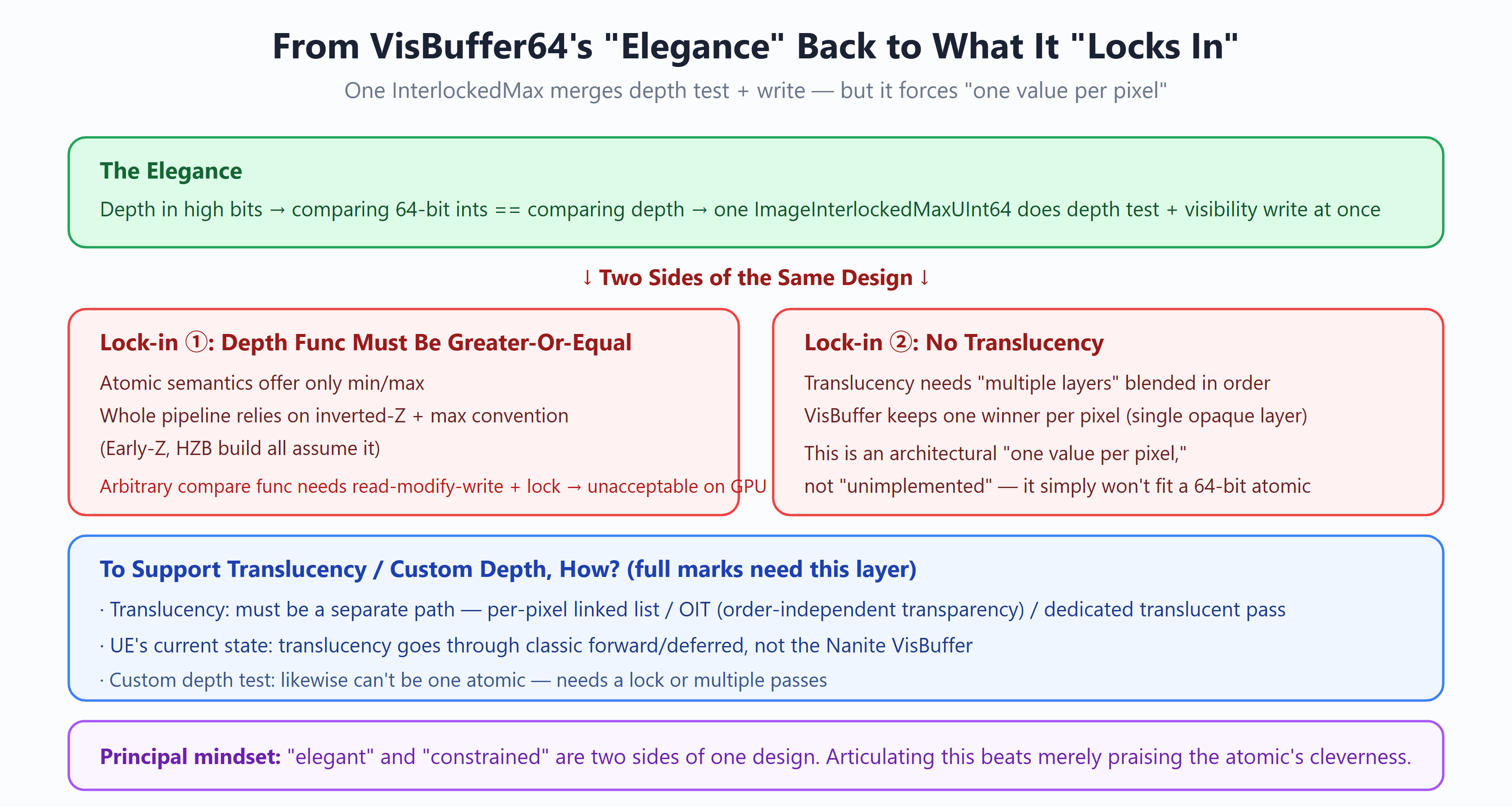
Model answer:
This question tests reasoning backward from an elegant implementation to its constraint boundary — “elegant” and “constrained” are two faces of the same design.
The elegance (Q1): depth in the high bits → comparing 64-bit integers equals comparing depth → one ImageInterlockedMaxUInt64 does the depth test + visibility write together.
What it locks in:
Lock-in ① — the depth function can only be Greater-Or-Equal: atomics have only min / max semantics. Depth in the high bits + InterlockedMax implements “greater depth wins” (under inverted-Z, the nearer wins). Switching to Less or any custom comparison can’t be expressed by a single atomic. And the whole pipeline depends on this convention — Early-Z and HZB construction both assume inverted-Z + max.
Lock-in ② — no translucency: translucency needs to keep multiple fragment layers and blend them in order (alpha blend). But the VisBuffer keeps one winner per pixel via InterlockedMax (single-layer opaque). So Nanite not supporting translucency is not “not yet implemented,” it’s the architectural “one value per pixel” — multi-layer info simply can’t fit this 64-bit atomic slot.
To support translucency / custom depth, how to change it (full marks must reach this layer):
- Translucency: must use a separate rendering path, can’t be folded into the VisBuffer. Options: per-pixel linked list (A-buffer), OIT (order-independent transparency), or a separate translucency pass. UE’s current state: translucency goes the traditional forward/deferred pipeline, not the Nanite VisBuffer.
- Custom depth test: likewise inexpressible by a single atomic, needing read-modify-write + a lock (unacceptable cost on the GPU) or multiple passes.
Principal thinking: being able to explain “elegant” and “constrained” are one thing — this 64-bit atomic’s elegance comes precisely from its assumption of “one opaque layer per pixel, monotonic depth comparison” — is a level above merely praising the atomic’s cleverness.
✅ Scoring rubric (by tier)
- 〔Pass〕 *”The VisBuffer uses one InterlockedMax atomic for both depth test and write, so the comparison can only be ‘larger wins,’ effectively fixed to GE depth comparison.”*
→ Why it scores: catches the core constraint — InterlockedMax itself can only do “take max,” equivalent to forcing one Greater-or-Equal depth comparison, with no custom comparison function. Right direction, hits the constraint essence. Pass.
- 〔Good〕 *”Depth is encoded in the high 64 bits, so one atomic max both compares depth and writes the corresponding visibility into the low bits. The whole pipeline depends on this convention — inverted-Z plus max, with Early-Z and HZB construction assuming it. Translucency can’t be done, because it stacks many layers while the VisBuffer keeps one winner per pixel.”*
→ Why it scores: states depth encoded in the high bits so InterlockedMax does “compare depth + write visibility” at once, knows the whole pipeline (Early-Z/HZB) is bound to inverted-Z+max, and points out the translucency conflict is “one winner per pixel vs. multi-layer blending.” Knows why.
- 〔Strong〕 *”The translucency conflict is architectural, not unimplemented: translucency needs to keep multiple layers per pixel blended in depth order, while the VisBuffer’s design stores one 64-bit winner per pixel (single-layer opaque) — these two are fundamentally opposed, so Nanite not supporting translucency is the inevitable result of this atomic design, not a missing feature. Custom depth likewise — atomic hardware semantics are only min/max, an arbitrary comparison needs read-modify-write plus a lock, and locking across millions of concurrent pixels on the GPU is unacceptable.”*
→ Why it scores: elevates “no translucency” from “missing feature” to “architectural inevitability” — one-value-per-pixel vs. multi-layer blending is fundamentally opposed — and gives a hardware-level reason for custom depth (atomics only min/max, arbitrary comparison needs RMW+lock, locking infeasible at GPU high concurrency). Dialectically explains “why this limit is two faces of the design.”
- 〔Bonus〕 *”To support translucency you can only use a separate path — per-pixel linked list, OIT, or a separate translucency pass; UE’s current state is translucency still goes the traditional raster pipeline, not crammed into Nanite’s 64-bit atomic. The elegance and the constraint here are two faces of the same design: precisely because it’s compressed into one atomic max can it do lock-free, high-throughput depth+visibility merging across millions of triangles, at the cost of single-layer opaque and GE-only comparison. Want flexibility, lose that throughput; want throughput, accept the constraint.”*
→ Why it scores: reaches the design-philosophy closure — not only gives translucency alternatives (per-pixel linked list/OIT/separate pass, and knows UE’s current state is translucency on the traditional pipeline), but unifies “elegant” and “constrained” as two faces of one design: one atomic max buys lock-free high throughput, at the cost of single-layer opaque + GE comparison. This “performance and flexibility are two sides of one coin” dialectical summary is the full-mark view.
⛔ Red flags (what’s wrong / why / what’s correct)
- “Nanite not supporting translucency is just unimplemented; a future version will add it.”
– What’s wrong: it’s not an implementation-progress issue, it’s a fundamental VisBuffer constraint. One 64-bit winner per pixel can physically only represent single-layer opaque, and translucency’s ordered multi-layer blending has nowhere to go.
– Correct: it’s an architectural opposition (one-value-per-pixel vs. multi-layer blending); supporting translucency requires a separate OIT/linked-list/pass, not patchable into the VisBuffer.
- “InterlockedMax can max or be configured for other comparisons; switch to InterlockedMin or custom to support other depth tests.”
– What’s wrong: atomic hardware provides only fixed min/max semantics; an arbitrary comparison function needs read-modify-write plus a lock for concurrency correctness, and locking across millions of concurrent pixels on the GPU is unacceptable.
– Correct: bound by atomics having only min/max, the VisBuffer picks inverted-Z + max (GE) and the whole pipeline (Early-Z/HZB) is hard-bound to this convention; you can’t freely swap the comparison.
- “Depth and visibility are written in two passes — atomic-compare depth first, then write visibility.”
– What’s wrong: two writes aren’t atomic; when two pixels race you can get a tear where the depth won but the visibility was overwritten by another.
– Correct: depth encoded in the high 64 bits, visibility in the low, one InterlockedMax does compare and write together, with “high bits dominate ordering” ensuring the winner’s visibility and its depth land atomically.
🕳️ Plausible-but-wrong traps (sound right, only half-understood)
- “The VisBuffer uses atomic max for the depth test.” — The half-truth: only half right. The key isn’t “does the depth test,” it’s that with depth in the high bits, one atomic max does both “depth compare + visibility write” — compressing two steps into one atomic, removing the separate visibility-write step.
- “Translucency needs blending, and Nanite didn’t implement blending so it’s unsupported.” — The half-truth: says “didn’t implement,” but it’s “can’t.” The VisBuffer structurally has one winner slot per pixel, while translucency needs multiple layers per pixel blended in order — the data structure can’t hold it, not a missing chunk of blending code.
- “Use InterlockedMin to support forward Z (near wins).” — The half-truth: in theory min can pick the nearer, but it ignores the whole-pipeline binding. The whole line (Early-Z, HZB construction) is hard-wired to the inverted-Z + max convention, and swapping one atomic direction conflicts with all HZB/Early-Z assumptions — not a one-call change.
🔍 Follow-up probes (the interviewer drills down)
- Why can one InterlockedMax handle both the depth test and the visibility write? How is the data laid out? → Put depth in the high 64 bits and the visibility ID in the low; atomic max compares the whole 64-bit value, dominated by the high-bit depth, so the max winner’s low-bit visibility is written atomically together with the depth — both in one op.
- Why does InterlockedMax fix it to GE-only depth comparison? Can you swap the comparison function? → Because atomic hardware has only fixed min/max semantics, max equals “larger wins” i.e. GE; an arbitrary comparison needs read-modify-write plus a lock, unacceptable across millions of concurrent GPU pixels, so the comparison is locked.
- Why does this design directly cause Nanite to not support translucency? → Because the VisBuffer stores one 64-bit winner per pixel (single-layer opaque), while translucency needs multiple layers per pixel blended in depth order, and the one-value-per-pixel structure simply can’t hold multiple layers — an architectural opposition, not a missing feature.
- If you really had to support translucency in the engine, how? How does UE handle it now? → Use a separate set: per-pixel linked list, OIT, or a separate translucency pass, not crammed into Nanite’s 64-bit atomic. UE’s current state is translucency keeps going the traditional raster pipeline, handled separately from Nanite’s opaque VisBuffer.
<a name=”q21″></a>
Q21. (System design) A forest of 100,000 trees (millions of triangles each, wind, collision, distant GI) — how would you design it? Rationale and risks?

Model answer:
No single right answer; this tests whether you can thread the prior knowledge into a trade-off-aware plan and identify the traps. I’ll cover selection + risks + pragmatic landing.
① Geometry — Nanite Foliage (Voxel + Instancing): the unique geometry stored once, referenced 100,000 times, memory from terabytes to gigabytes; distant trees auto-become voxel blobs via distance-driven LOD.
② Wind — Nanite Skinning: bone simulation (not WPO, voxel-path-supported); AnimationMinScreenSize keeps distant trees unskinned to save cost.
③ GI — Lumen HWRT: but the trees’ ray-tracing BLAS uses a coarse LOD (large StreamOutCutError), Offscreen.LODBias lowers off-screen quality, and MaxBuiltPrimitivesPerFrame controls the BLAS build budget.
④ Shadows — VSM: matched to Nanite’s geometric density. ⚠ But 100,000 shadow casters + trees swaying in wind → frequent VSM page-cache invalidation (a tree moves and its page invalidates); this dynamic-invalidation cost must enter the budget.
⑤ Collision — the trap!: Nanite Foliage is still Experimental in 5.7, with incomplete collision/physics. So collision can’t rely on Nanite — use separate simplified collision bodies (convex hulls/capsules). And 100,000 trees can’t each have a collision body (it’d blow up), so dynamically enable collision only for trees near the character, or use procedural near-distance collision proxies. This is the easiest trap to fall into.
Risk identification (full marks must list proactively): Foliage experimental, collision gap (biggest trap), VSM dynamic-invalidation cost, BLAS build spikes, streaming bandwidth (needs SSD), wind’s skinning cost, massive-instance culling / Instance Hierarchy pressure.
Pragmatic landing: build a demo first to validate the 60 fps budget, carve collision/physics out as a special case rather than enabling everything on paper. Being able to say this matters more than listing the plan in full.
✅ Scoring rubric (by tier)
- 〔Pass〕 *”Geometry uses Nanite Foliage, 100,000 trees share one geometry via instancing references, wind uses Nanite Skinning not WPO, distant uses Nanite’s auto LOD into voxels, GI uses Lumen.”*
→ Why it scores: maps geometry/wind/LOD/GI each to the right Nanite subsystem (Foliage instancing, Skinning not WPO, distance voxels, Lumen) — the overall skeleton is right. Pass.
- 〔Good〕 *”The geometry key is the unique geometry stored once referenced 100,000 times, dropping terabytes to gigabytes. Wind goes bone skinning not WPO, because the voxel path doesn’t support WPO, and distant uses AnimationMinScreenSize to keep trees unskinned to save cost. GI uses Lumen HWRT with a coarse tree BLAS. Collision is a trap, can’t count on Nanite, needs separate simplified collision bodies.”*
→ Why it scores: states the instancing storage gain (TB→GB), why wind goes bones (voxels don’t support WPO), the not-skinning-distant constant (AnimationMinScreenSize), and already realizes collision is a trap to handle separately. Knows why, and catches the key collision trap.
- 〔Strong〕 *”For GI, the trees’ ray-tracing BLAS uses StreamOut to export a coarse LOD (large cut error), off-screen drops another notch via Offscreen.LODBias, and the BLAS build budget is controlled so 100,000 don’t build in one frame. Collision must be carved out: Nanite Foliage collision/physics is still Experimental and incomplete in 5.7, 100,000 trees can’t each have a collision body, so dynamically enable simplified convex/capsule collision only for trees near the character. Shadows use VSM, but beware the cost of trees moving among 100,000 casters invalidating page cache.”*
→ Why it scores: explains each subsystem’s “trade-off and cost” — the GI triad of coarse BLAS + off-screen bias + build budget, the pragmatic “enable only near the character” collision, the VSM page-cache invalidation risk. Not just piling up terms but pointing out each block’s risk and countermeasure — the global trade-off ability of system design.
- 〔Bonus〕 *”List the risks by tier: Foliage collision/physics experimental (incomplete in 5.7), VSM dynamic-invalidation cost, BLAS build spikes, streaming bandwidth needing SSD. Pragmatic landing is a small demo first to validate whether the 60 fps budget holds, then carve collision/physics out as special handling rather than assuming Nanite covers all. The ‘a tree moves and the VSM page invalidates’ point deserves a special flag, because 100,000 trees in continuous wind is continuous invalidation that can directly eat VSM’s cache benefit.”*
→ Why it scores: reaches the engineering-pragmatic level — lists risks fully by “experimental feature / dynamic invalidation / build spike / bandwidth,” gives the landing path “demo to validate budget + carve out collision,” and specially notes that VSM’s page cache can be defeated under continuous wind (100,000 continuous invalidations cancel the cache benefit) — a subtle but lethal point. From the paper plan to a deliverable engineering judgment, the finale a full-mark system design should have.
⛔ Red flags (what’s wrong / why / what’s correct)
- “Enable Nanite collision on each of the 100,000 trees and hand physics to Nanite.”
– What’s wrong: Nanite Foliage’s collision/physics is still Experimental and incomplete in 5.7, can’t be relied on; and a collision body on each of 100,000 trees is unrealistic for memory and the physics solver.
– Correct: collision must be carved out as separate simplified collision bodies (convex/capsule), dynamically enabled only for trees near the character, none for distant ones.
- “Do the trees’ wind with WPO vertex offset, Nanite supports it all.”
– What’s wrong: the forest geometry goes Nanite Foliage’s voxel path, and voxels don’t support WPO (no vertex stage).
– Correct: wind goes Nanite Skinning bone skinning (the voxel path supports bones), with AnimationMinScreenSize keeping distant trees unskinned to save cost.
- “With VSM shadows, the 100,000 trees’ shadows are stable, no worries.”
– What’s wrong: VSM saves cost via page cache, but a tree swayed by wind invalidates its page, and 100,000 trees in continuous wind continuously trigger page-cache invalidation, with cost possibly high or even canceling the cache benefit.
– Correct: list “dynamic-invalidation cost” as an explicit risk, assess the impact of wind frequency on VSM cache hit rate, and limit wind amplitude or shadow range if needed.
🕳️ Plausible-but-wrong traps (sound right, only half-understood)
- “Nanite Foliage holds all 100,000 trees’ geometry, so the forest can hand everything to Nanite.” — The half-truth: geometry and rendering are indeed handled, but collision/physics isn’t. 5.7 Foliage collision is still Experimental, and assuming collision is Nanite-covered too is the classic half-understanding — collision must be carved out separately.
- “Distant trees become voxel blobs automatically, nothing to manage.” — The half-truth: voxelized LOD is automatic, true, but “whether to skin distant trees” needs active control via AnimationMinScreenSize, and voxel wind goes per-brick single bone not WPO — not fully automatic zero-config; skinning cost must be actively culled.
- “Trees do GI with Lumen HWRT, build the BLAS and you have global illumination.” — The half-truth: ignores BLAS LOD and budget. The trees’ BLAS must use StreamOut to export a coarse LOD (large cut error) to save cost, 100,000 also needs MaxBuiltPrimitivesPerFrame to prevent build spikes and Offscreen.LODBias for off-screen — not blindly building full-precision BLASes.
🔍 Follow-up probes (the interviewer drills down)
- 100,000 trees, millions of triangles each — why doesn’t geometry blow up memory? → Because Nanite Foliage uses instancing: the unique geometry is stored once in VRAM, all 100,000 being references to it (with their own transforms), so storage drops from a theoretical terabytes to gigabytes — not actually 100,000 copies of geometry.
- How exactly is wind-swaying implemented? Why not WPO? → Via Nanite Skinning bone skinning, the voxel path using per-brick single-bone-driven offset. Not WPO because the forest goes the voxel path, voxels reconstructed on the fly from depth with no vertex stage where WPO’s vertex offset has nowhere to apply; distant then turns skinning off via AnimationMinScreenSize to save cost.
- What do you think is the biggest trap in this plan? → Collision. Nanite Foliage’s 5.7 collision/physics is Experimental and incomplete, can’t be relied on; 100,000 trees can’t each have a collision body. Only carve out separate simplified collision (convex/capsule) and dynamically enable it only near the character. Next is the cost of VSM page cache continuously invalidating under continuous wind.
- Would you dare ship this plan directly? How to land it and reduce risk? → Not all-in directly. Build a small demo first to measure the 60 fps budget (geometry/skinning/BLAS/VSM shares), carve collision/physics out as special handling, confirm streaming bandwidth on SSD holds, then scale up gradually; keep watching Foliage collision experimental, BLAS build spikes, VSM dynamic invalidation.
Workflow and Platform Landing (Q22–Q23)
<a name=”q22″></a>
Q22. A team upgrading from UE4 to UE5 enabling Nanite — how exactly does the art workflow change? Old vs. new flow, required settings, acceptance.
Model answer:
This question isn’t “how great Nanite is,” it’s whether you can articulate how the workflow’s labor shifts — Nanite doesn’t make the art work vanish, it swaps “decimate-to-budget, bake LODs” for “cleanup + setup + acceptance.”
Old vs. new flow:
The old workflow is a chain of repeated negotiation with the “triangle budget”: sculpt high-poly → retopo decimate (compromise to budget) → bake normals/AO → author LOD0~4 by hand or semi-automatically → tune switch distances in engine → miss the perf target and go back to decimate more. Among these, authoring and maintaining the LOD chain is repeated labor that scales linearly with asset count — a standing tax on content throughput for open-world projects.
The Nanite workflow is much shorter: high-poly (sculpt/scan) → basic cleanup (watertightness, UV, material merge) → import and tick Enable Nanite (LOD chain auto-built by the engine) → set Fallback and precision parameters → accept with visualization tools. But be clear-eyed: this isn’t zero work, it’s a labor shift — material merge still matters (fewer slots, more efficient shade binning), watertightness and UV quality still need managing (affecting simplification quality and implicit-tangent precision), and there’s a new cost from huge high-poly source files: DCC file management and version-control storage pressure, which didn’t exist before.
Two required settings (the Tech Lead should spell these out):
- Fallback Mesh: a traditional mesh auto-decimated from the source, rendering as a stand-in on Nanite-unsupported platforms and by default also serving complex collision and lightmap baking. Quality is controlled by
FallbackTarget/FallbackPercentTriangles/FallbackRelativeError(FMeshNaniteSettingsinEngineTypes.h), default Auto. Cross-platform projects must set it explicitly and test on low-end hardware — too coarse and low-end quality collapses, too fine and package size and memory are paid for nothing. - Position Precision: default Auto, the engine deciding the quantization step by mesh density. Two asset classes warrant manual setting: seam-precision-sensitive modular kit pieces (quantization staircases amplify at seams), and abnormally large single objects. Also an on-demand option
bExplicitTangents— enableable for assets sensitive to normal-map quality at mirrored UVs/seams, at the cost of larger vertex data.
Limits artists should know: translucency, Morph unsupported (mixing with the traditional pipeline in-frame is fine, translucent objects keep going the old pipeline); WPO works but costs (affected clusters take the programmable raster path, raster cost rises, large offsets also need bounds-inflation handling); the voxel path supports neither WPO nor Displacement.
Acceptance tooling: use r.Nanite.Visualize to cycle Overdraw / Triangles / Clusters per scene, focusing on overdraw hotspots (usually from large Masked areas or thin-sheet stacking), with stat GPU for per-pass Nanite timings. Let data, not intuition, decide on/off.
✅ Scoring rubric (by tier)
- 〔Pass〕 *”After Nanite artists don’t hand-author LODs, high-poly goes straight into the engine, saving the decimation and LOD-baking work.”*
→ Why it scores: catches the most core change — the LOD chain disappears, high-poly goes straight in. Right direction. Pass.
- 〔Good〕 *”The old flow is high-poly→decimate→bake normals→author LOD→tune distances, every step negotiating with the budget, the LOD chain being repeated labor scaling linearly with assets. Nanite is high-poly→cleanup→tick Enable→set Fallback/precision→accept. But it’s not zero work, it swaps decimation for cleanup and setup, with material merge, UV, watertightness still to manage.”*
→ Why it scores: fully contrasts old and new flow and accurately notes “labor shifts, doesn’t vanish.” Knows why.
- 〔Strong〕 *”Two required settings: Fallback Mesh controls unsupported-platform downgrade and complex collision/lightmap baking, must be set explicitly cross-platform and tested on low-end; Position Precision default Auto, but modular kit pieces and extreme-scale objects need manual. Plus the version-control storage pressure from huge high-poly source files, a cost unique to the new flow. Acceptance can’t be eyeballed, use r.Nanite.Visualize for overdraw hotspots.”*
→ Why it scores: covers “required settings + why required + new cost + engineering acceptance” fully, showing the full-chain view from art to TA to programmer.
- 〔Bonus〕 *”Fallback quality is controlled by FallbackTarget/PercentTriangles/RelativeError; note it’s not ignorable even on all-Nanite platforms — it also serves collision and lightmap baking by default. WPO under Nanite makes clusters take the programmable raster path raising raster cost, so artists should use WPO sparingly. bExplicitTangents is the fallback switch for mirrored-UV/seam-sensitive assets.”*
→ Why it scores: gives field-level evidence and the WPO cost mechanism, showing understanding at the implementation layer, not just reciting the flow.
⛔ Red flags (what’s wrong / why / what’s correct)
- “With Nanite on, artists don’t manage optimization at all, just pile on polygons.”
– What’s wrong: geometric polycount is indeed freed, but material slot count, UV quality, and watertightness still directly affect shading efficiency and simplification quality; translucency/Morph still unsupported, WPO still costs.
– Correct: it’s a labor shift — the decimate/bake-LOD work is gone, but cleanup, material merge, avoiding-the-limit-list pitfalls, and acceptance remain.
- “Fallback Mesh only matters on old Nanite-unsupported platforms; mainstream platforms can ignore it.”
– What’s wrong: Fallback by default also serves complex collision and lightmap baking, so even on all-Nanite target platforms its quality affects collision and baking results.
– Correct: fallback quality parameters must be set explicitly in any project, not treated as a corner that exists only for old platforms.
- “High-poly goes straight into the engine, so the art side’s storage and file-management pressure is actually lower.”
– What’s wrong: huge high-poly source files (sculpt/scan) make DCC file and version-control storage pressure a new cost unique to the new flow.
– Correct: runtime .uasset grows too, source files even more, and storage/version-management pressure rises rather than falls.
🕳️ Plausible-but-wrong traps (sound right, only half-understood)
- “The Nanite workflow is just ticking Enable at import, nothing else to do.” — The half-truth: ticking only triggers the auto build; the preceding cleanup (watertight/UV/material merge) and the following required settings (Fallback/precision) and acceptance can’t be skipped; saying “just tick it” distorts the workflow.
- “Fallback is just a low-poly LOD, same as traditional LOD.” — The half-truth: Fallback is a single fallback mesh auto-simplified from the source at build, serving “unsupported-platform downgrade + collision + baking,” not a discrete LOD chain switched by distance at runtime; Nanite runtime is continuous LOD (Q5).
- “Acceptance is just checking the image doesn’t break.” — The half-truth: overdraw hotspots are invisible to the eye and must be located via r.Nanite.Visualize’s overdraw view + stat GPU; eyeballing acceptance misses performance traps.
🔍 Follow-up probes (the interviewer drills down)
- Why is the LOD chain a “standing tax” in the old flow? → It’s repeated labor scaling linearly with asset count: each asset needs a LOD0~4 set, a high-poly revision redoes the whole downstream chain, and with many open-world assets that labor is a standing cost on content throughput.
- Since Nanite auto-builds LOD, why still manage UV and watertightness? → UV quality affects implicit-tangent derivation precision (Q16) and the UV error metric during simplification; watertightness affects simplification quality. These are build-quality inputs, not waived by LOD automation.
- What are the consequences of fallback being too coarse or too fine? → Too coarse: Nanite-unsupported platforms’ quality collapses, collision/baking distort; too fine: package size and memory paid for nothing (fallback data grows). So balance it by testing at min spec, not muddling through with the default.
- How do you explain to artists “WPO works but use sparingly”? → WPO makes affected clusters take the programmable raster path, raising raster cost, with large offsets also needing bounds-inflation handling; not unusable, but there’s a perf bill with heavy use, and dense WPO (e.g. legacy foliage) should be evaluated for moving to the Foliage voxel+bone path (Q9/Q17).
Probe prep: if asked “which assets should actually enable Nanite” — lead to Q7’s per-asset decision tree; if asked “how to downgrade on unsupported platforms” — lead to Q23.
<a name=”q23″></a>
Q23. How does Nanite do multi-platform compatibility? Which platforms are unsupported, what’s the downgrade, and why is mobile effectively unusable?
Model answer:
Nanite’s multi-platform strategy stands on three legs: a hardware-capability gate decides eligibility, the Fallback Mesh provides auto-downgrade, and cook-time two-way stripping trims data per platform.
Leg one — the hardware-capability gate. Whether Nanite runs at runtime is decided by a set of explicit gates (DoesRuntimeSupportNanite in RenderUtils.cpp): platform support (data-driven GetSupportsNanite) + GPUScene support + project-level r.Nanite.ProjectEnabled + 64-bit image atomics available + not currently forward shading. Among these, 64-bit atomics is the hardest gate (NaniteAtomicsSupported): GRHISupportsAtomicUInt64 must be true; on Windows r.Nanite.RequireDX12=1 by default allows only DX12 or Vulkan (DX11 excluded); DX12 also requires SM6.6 atomic support — old Windows 10 (pre-1909) or old drivers simply don’t qualify. This gate is exactly the hardware-layer projection of VisBuffer64’s InterlockedMax (Q1).
Platform matrix (5.7 state):
- Full support: PC (DX12 SM6.6 / current Vulkan), PS5, Xbox Series, desktop Metal (Apple Silicon);
- Effectively unusable: mobile (see below);
- Unsupported → fallback: last-gen consoles PS4/XB1, DX11/old drivers.
Leg two — Fallback Mesh auto-downgrade. Each Nanite mesh carries a traditional mesh auto-simplified at build. On Nanite-unsupported platforms/RHIs, rendering auto-switches to the fallback going the traditional pipeline — one asset, two forms, no second content set to maintain. Note the fallback by default also serves complex collision and lightmap baking, so its quality parameters can’t be ignored even on all-Nanite target platforms.
Leg three — cook-time two-way strip. On Nanite-capable platforms, cook can strip fallback mesh data to save package size (ShouldStripNaniteFallbackMesh, StaticMesh.cpp, driven by the platform-level ShouldStripNaniteFallbackMeshes() interlocking with the asset-level GenerateFallback); unsupported platforms strip Nanite data instead. Each platform ships only what it uses — two forms ≠ double package.
Why mobile is effectively unusable (the crux): 64-bit image atomics are broadly missing on mobile GPUs. Even taking the UlongType uint2 emulation path still requires the compiler to support 64-bit atomic instructions (Platform.ush:1352) — so Nanite on mobile isn’t “slow,” it simply won’t run, a hardware-capability reason, not an Epic product strategy. The VisBuffer’s “depth+ID in one atomic write” design fundamentally depends on 64-bit atomics, and mobile lacking this foundation makes the whole thing not hold.
Landing checklist: pin the min spec (cover DX11/old-driver users? If yes → fallback quality is P0); art acceptance covers both Nanite and fallback forms; split package budget per platform across Nanite / fallback data; on supported platforms use per-platform scalability (e.g. r.Nanite.MaxPixelsPerEdge) to tune quality tiers.
✅ Scoring rubric (by tier)
- 〔Pass〕 *”Nanite isn’t supported on all platforms; unsupported ones use the fallback traditional mesh; mobile is basically unusable.”*
→ Why it scores: catches the three core conclusions “platforms split supported/unsupported + fallback downgrade + mobile limited.” Right direction. Pass.
- 〔Good〕 *”Whether it can be enabled is decided by a set of gates, the most crucial being 64-bit image atomics, with Windows defaulting to only DX12/Vulkan. Unsupported platforms auto-switch to the fallback mesh on the traditional pipeline, one asset two forms. Mobile basically won’t run for lack of 64-bit atomics.”*
→ Why it scores: states the gate’s core conditions (64-bit atomics + DX12/Vulkan) and the fallback two-form mechanism, and knows the direct reason for mobile’s limit. Knows why.
- 〔Strong〕 *”Three legs: the hardware gate (64-bit atomics the hardest gate, the hardware-layer requirement of VisBuffer’s InterlockedMax), Fallback Mesh auto-downgrade (also serving collision and lightmap baking by default), and cook-time two-way strip (supported platforms strip fallback, unsupported strip Nanite, each shipping only its own data). Mobile is unusable because 64-bit image atomics are broadly missing, with even uint2 emulation needing compiler 64-bit atomic support — a hardware-foundation issue, not performance.”*
→ Why it scores: covers all three legs, attributes “mobile unusable” precisely to hardware capability (not performance), and points out its causal link to Q1’s VisBuffer design — system-level understanding.
- 〔Bonus〕 *”The gate is DoesRuntimeSupportNanite in RenderUtils.cpp, the 64-bit atomic check in NaniteAtomicsSupported — default RequireDX12=1 excludes DX11, DX12 also needs SM6.6 atomics, old Win10 pre-1909 doesn’t qualify. Cook strip is ShouldStripNaniteFallbackMesh in StaticMesh.cpp, interlocking platform-level and asset-level GenerateFallback. Two forms ≠ double package precisely because of this two-way strip.”*
→ Why it scores: gives function-level evidence (DoesRuntimeSupportNanite/NaniteAtomicsSupported/ShouldStripNaniteFallbackMesh) and specific CVars (RequireDX12, SM6.6), proving reading at the source level.
⛔ Red flags (what’s wrong / why / what’s correct)
- “Nanite runs on all platforms; mobile is just a bit slower.”
– What’s wrong: mobile isn’t slow, it’s that 64-bit image atomics are broadly missing, the VisBuffer’s atomic-write foundation doesn’t hold, and it basically won’t run.
– Correct: mobile is effectively unusable for hardware-capability reasons (lacking 64-bit atomics) — a can-it-run issue, not a fast-or-slow one.
- “Two forms (Nanite + fallback) double the package.”
– What’s wrong: cook-time two-way strip — supported platforms keep only Nanite data stripping fallback, unsupported keep only fallback stripping Nanite, each shipping only its own.
– Correct: two forms ≠ double package, ensured by cook two-way strip so each platform packages only what it actually uses.
- “Fallback Mesh is just for rendering on old platforms; all-support platforms can strip it and ignore quality.”
– What’s wrong: fallback by default also serves complex collision and lightmap baking, and poor quality affects collision and baking; and whether to strip is decided by interlocking platform-level/asset-level switches, not arbitrary.
– Correct: fallback quality must be managed explicitly in any project; whether to strip is decided jointly by the platform policy ShouldStripNaniteFallbackMeshes + the asset-level GenerateFallback.
🕳️ Plausible-but-wrong traps (sound right, only half-understood)
- “Nanite needs DX12 because DX12 performs better.” — The half-truth: needing DX12/Vulkan isn’t for performance, it’s because 64-bit image atomics are required, which DX11 can’t provide (default RequireDX12=1 excludes DX11); a capability gate, not a performance preference.
- “Mobile will support Nanite once drivers update.” — The half-truth: the core blocker is hardware/compiler support for 64-bit image atomics, not solvable by driver tuning; even the uint2 emulation path needs compiler 64-bit atomic instructions, and without the foundation it doesn’t hold.
- “Fallback is simplified on the fly at runtime.” — The half-truth: fallback is a mesh simplified offline from the source at build (cook) time, not generated at runtime; runtime only chooses to render the Nanite form or the fallback form by platform capability.
🔍 Follow-up probes (the interviewer drills down)
- What exactly does the Nanite-enablement gate check? → DoesRuntimeSupportNanite: platform GetSupportsNanite + GPUScene + r.Nanite.ProjectEnabled + 64-bit atomics (NaniteAtomicsSupported) + not forward shading, all satisfied to enable.
- Why is 64-bit atomics the hardest gate? → Because VisBuffer64 uses one InterlockedMax to pack depth + visibility ID for an atomic write (Q1), which depends on 64-bit image atomics; without it the whole visibility write can’t guarantee concurrency correctness, so it’s a foundation-level hard dependency.
- How exactly does the two-way strip decide which to strip? → ShouldStripNaniteFallbackMesh, driven by the platform-level ShouldStripNaniteFallbackMeshes() and the asset-level GenerateFallback: Nanite-capable platforms strip fallback, unsupported strip Nanite data, so each cooked platform contains only what it uses.
- A project shipping to both PS5 and Switch (mobile-class GPU) — what about Nanite? → PS5 fully supports Nanite, enable it; Switch-class mobile GPUs lacking 64-bit atomics are effectively unusable and must use the fallback mesh on the traditional pipeline, with fallback quality tuned to Switch’s min spec, and cook stripping Nanite data for Switch keeping only fallback.
Probe prep: if asked “why VisBuffer must use 64-bit atomics” — lead to Q1; if asked “how to set fallback quality” — lead to Q22’s required settings.
Closing
The 24 questions progress in four groups:
- Q1–Q6 core machinery — VisBuffer / software raster / fixed-point / DAG / continuous LOD / two-pass occlusion, testing low-level fundamentals;
- Q7–Q11 architecture trade-offs + rendering vision — asset guidelines, cost structure, Skinning, the matched-set synergy, the build-your-own judgment, testing Tech Lead practice and Principal vision;
- Q12–Q16, Q24/Q25 build / shading at the source level — graph partitioning, error monotonicity, paged Transcode, ShadeBinning, implicit tangents, quantization precision, METIS selection and vertex strip encoding, testing whether you’ve actually read the engine;
- Q17–Q23 5.7 new features + architecture finale — Foliage voxels, Skinning, Lumen HWRT, the limit-reasoning, forest system design, art workflow, multi-platform landing, testing knowledge freshness and system judgment.
Each question’s structure is: question → model answer (source-cited) → scoring rubric (four tiers) → red flags → plausible-but-wrong traps → follow-up probes. All source references are based on an Unreal Engine 5.7 source build; line numbers may drift across versions; figures are the author’s own.
*Based on a UE 5.7 source build of E:/Project/UE; line numbers may drift across versions. Figures are the author’s own.*