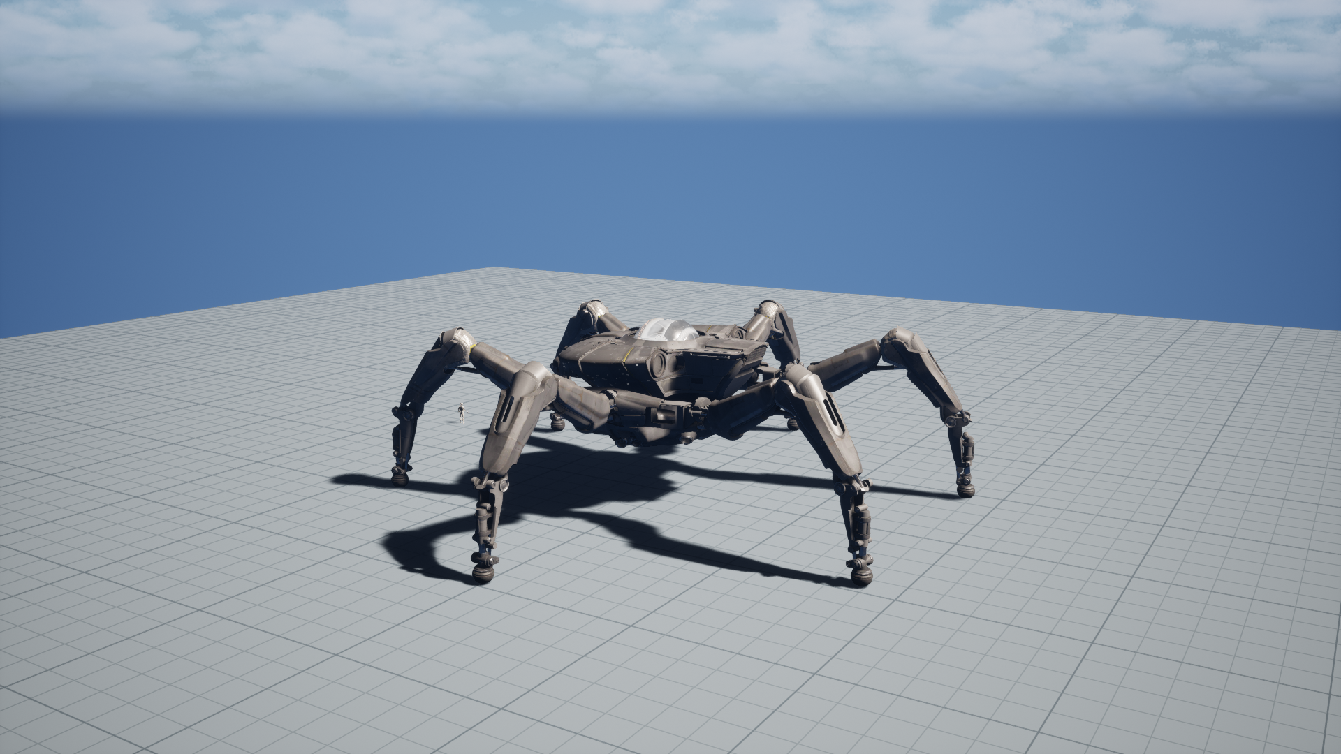
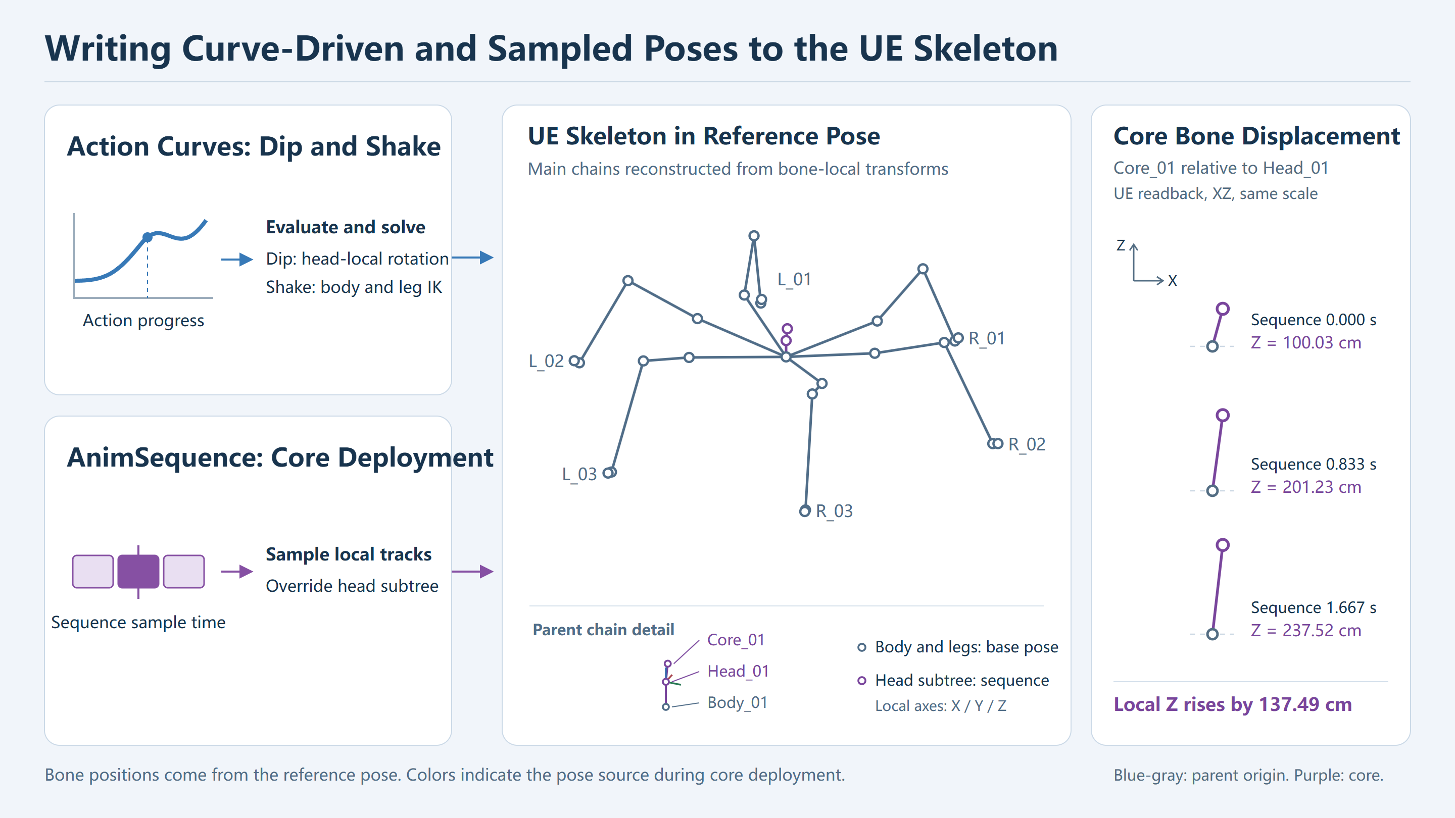
When the giant robot dips its head, an action curve drives head pitch while the body and legs maintain their support pose. Core deployment takes a different route. The runtime samples an imported UE animation sequence (AnimSequence) and applies the resulting local transforms to the head subtree. Both paths use the same UE skeleton. They differ in the data they start with and the bones they update.
Part 1 covered stance anchors, foot state, and leg inverse kinematics (IK). This part follows three examples through the asset pipeline and into UE: the head dip, the body shake, and core deployment.
Contents
- Mesh, Reference Skeleton, and Animation Data
- Action References, Curve Sampling, and Runtime Parameters
- Bone Track Mapping and UE Pose Updates
- Head Dip: Curve Inputs and Head Rotation
- Body Shake: Body Transform and Sole Constraints
- Core Deployment: Sequence Sampling and Subtree Override
- Stomp Curves and the Force-Control Interface
- Asset-Version Compatibility and Runtime Verification
The head-dip footage shows head pitch against the body’s support pose. The frame comparison later pairs the visible motion with the curve value, blend weight, and output angle.
Mesh, Reference Skeleton, and Animation Data
To find out why a part moves, identify the bones that influence it and trace their pose inputs along the parent chain.
| Resource | What it provides | Integration check |
|---|---|---|
| Skeletal Mesh and LODs | Render geometry, skin weights, and representations for each level of detail | Check which bones drive the geometry in a common reference pose. Check bone reduction separately for each LOD. |
| Reference Skeleton | Bone names, parent indices, and reference local transforms | Follow the actual hierarchy through the body, legs, head, and core. |
| Physics Asset | Rigid bodies, collision shapes, and constraints | Inspect the instantiated proxies and collision configuration separately from the visible skeleton. |
| Action data repository | Action references, curves, and timing parameters | Resolve the reference and evaluate the channel at the sample time. |
Animation sequence (AnimSequence) |
Bone transforms sampled over time | Decode the tracks, check the bone mapping, and compare with UE readback. |
A name can appear in mesh, skeleton, and animation data while referring to different index spaces. Track 12 in decoder output cannot be assigned to UE bone 12 on index alone. A wrong target bone or parent can displace the head and propagate the error to its descendants. Keep the mapping between track index, source bone identity, and target index.
An animated leg can include joints, accessory bones, and skinned bones. The flat-ground force controller in Part 1 uses a body and independent foot proxies. These are the physical representations chosen for that experiment. A collider with the same name as a bone still needs to be checked against the objects the simulation instantiates and uses.
The reference pose is the skeleton’s static set of reference transforms. The support base pose is the current pose supplied by the body and leg solve before the action layer applies its overrides. In the core deployment demo, the standing result supplies the support base pose and the sequence updates the head subtree. Additive animation uses the base reference specified by its own asset settings.
Skinning, Bone Poses, and Physical Contact
For a frame from core deployment, first check that the sampled track writes to the core bone. Then check that the mesh’s skin weights carry its motion to the intended vertices. A mesh change cannot correct a track mapped to the wrong bone or parent chain.
In Part 1, each foot proxy reports the rigid body’s world position, rotation, and contact state. The rendered foot bone supplies a skinning transform and its origin can sit above the contact surface. Writing a pose to the skeletal mesh component can change the visible result immediately. The proxy moves through control and physics stepping. In the head dip and body shake, sole anchors serve as kinematic targets. The rigid-body contact and load evidence comes from the separate physics runs in Part 1.
For one front foot, distinguish the reference bone origin, the solved bone origin, and the sole contact point. If T is the foot bone’s world transform and d is its local offset to the sole, the world-space sole position is T applied to d. Measuring bone-origin height includes that offset in the result, and the offset rotates with the foot. The sole errors below compare the sole with its anchor in world space. Head rotation comparisons use the relevant bone and transform space.
Mapping Animation Tracks to Target Bones
Animation binding involves the source sequence’s track index, the identity of the source bone attached to that track, and the target component’s bone index. The source order, target reference skeleton order, and set of bones used for rendering can differ. Record the track index, source bone name, target bone name, and target parent. Add the mesh and skeleton identities when comparing frames.
Suppose a track translates the core slider under the head. Writing it to the head bone moves every descendant. Writing it to the core in component space when it was authored in parent-local space sends the core along the wrong axes when the body turns. Both mistakes can look like a part rising in a static front view. A pose with a rotated body makes target-bone, parent, and space errors easier to distinguish.
The script resolves parent indices to bone names. It finds the head root through HeadBoneName and walks upward from each available bone to find its descendants. It checks that the root is present and rejects results containing leg or foot bones. If names or the hierarchy change, verify the boundary against the new skeleton. Use asset exports for the complete skeleton, per-LOD bone lists, and reference transforms.
Pose Inputs for the Three Actions
| Demo | Action input | Local pose update | Runtime evidence |
|---|---|---|---|
| Head dip | Action curves and retained source pose samples | Reconstruct head-local rotation and blend it into the support base pose | Head angles and footage |
| Body shake | Action curves and retained source pose samples | Update body and head transforms and re-solve leg IK against world-space sole anchors | Head angles, footage, and separately recorded sole-to-anchor residuals |
| Core deployment | Imported UE animation sequence | Sample the head subtree at sequence time and retain the support base pose elsewhere | Sequence sample time and core-bone transforms |
Curve evaluation produces action parameters. The pose code turns them into rotations, translations, and foot targets. A sequence track already describes a bone transform. Integration resolves its target bone, samples it, and composes it along the current parent chain.
Action References, Curve Sampling, and Runtime Parameters
The head dip and body shake use the same reconstruction path. Resolve the action and channel, convert the runtime clock to curve query time, then apply the sampled values with the action’s blend-in and blend-out weight.
Action Records and Curve Channel Mapping
The script selects an action record in GeneratedData and reads the head-bone name, parameterization mode, and head-animation flag from Settings. This path requires mode 1 and enabled head animation. The channel map selects the field, EditorCurveData.Keys supplies the keyframes, and the linear sampler evaluates them.
The wrapper records the channel, query time, and fallback supplied by the caller. A zero output may come from a curve that evaluates to zero or a missing channel with a zero fallback. The available code confirms that the wrapper forwards the default and records the query. The sampling function still needs to be checked for the exact behavior of an empty channel.
Body translation, body pitch/yaw/roll, and head pitch/yaw/roll are separate channels. Head rotation becomes a quaternion. Body translation depends on the reference height and scene datum. To verify integration, follow the action reference through channel resolution, evaluation, and space conversion, then match each returned value to the field used by the pose code.
Recording Clock, Active Time, and Normalized Progress
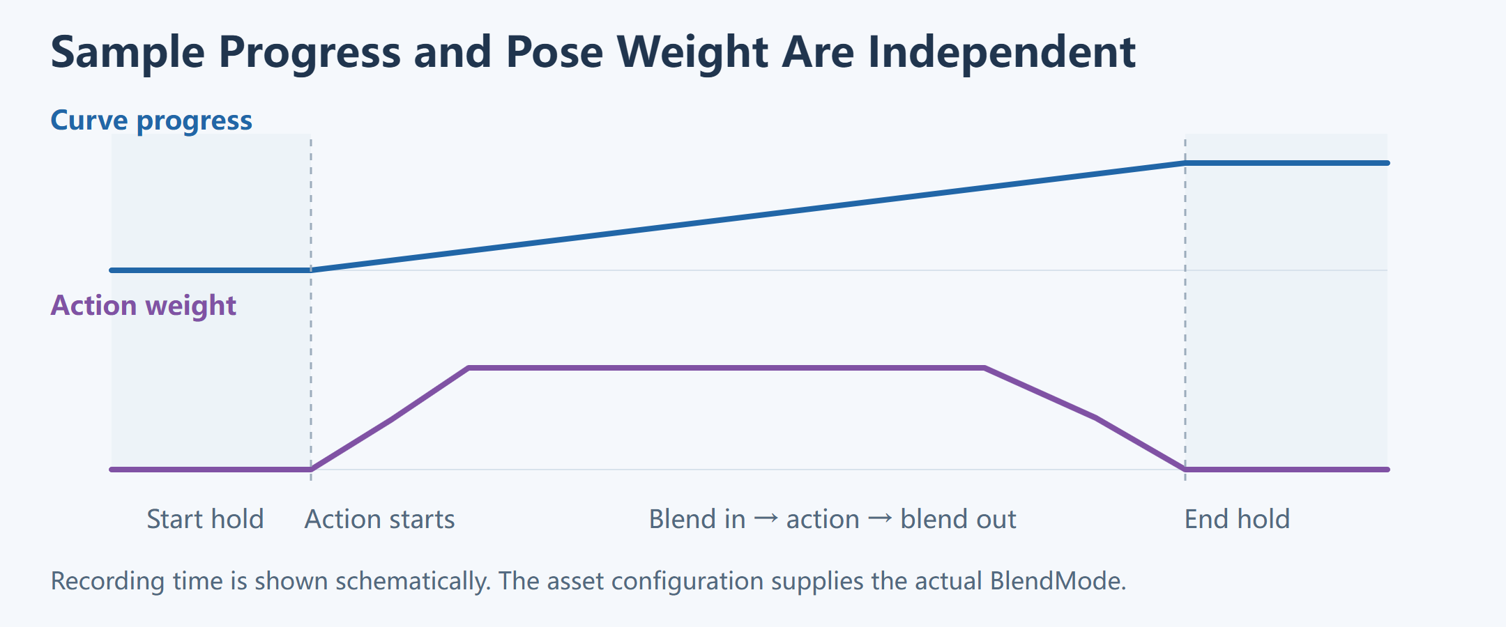
The head-dip and body-shake generators produce samples at 30 Hz. They read the action length from OriginalAnimationLength and leave an extra second on either side to show the start and end. Let t be the recording clock derived from the generated frame index and L the source action length.
t        = frame / 30
active   = clamp(t − 1 s, 0, L)
progress = active / L
During the first second, the query stays at zero. After the action, it holds at the endpoint. The reconstruction sets the action weight to zero outside the active interval, so the curve can retain its last value while the visible pose returns to the support base pose.
For a 2 s action, video time t = 1.5 s gives 0.5 s of active time and normalized progress 0.25. Query a seconds-based track at 0.5 and a normalized curve at 0.25. A time-domain error shifts when the keys are sampled. A slow fade-in reduces the output even when the samples align. Logging progress alongside weight separates the two.
The stomp in Part 1 uses a different contract. Its main action and recovery each last 2 s, and the denominator remains the main action length. Recovery runs from progress 1 to 2. The head dip and body shake use their own source lengths. Check the valid interval before reusing the conversion.
Keyframe Interpolation and Pose Weight
For adjacent keys (t0, v0) and (t1, v1), the linear segment is evaluated as follows.
u = (t − t0) / (t1 − t0)
value = v0 + u × (v1 − v0)
Evaluate t in the keyframe time domain. Constant extrapolation holds the endpoint outside the key range. The blend weight then controls how much of that sampled value contributes to the pose. Other formats need to be checked against their own interpolation and extrapolation fields.
For a scalar channel, let vAction be the sampled value, vBase the support base value, and w the independent weight. A linear blend gives vBase + w × (vAction − vBase). Even if the curve holds its final value, w can change. Bone rotations use a blend suited to their rotation representation.
Blend Windows and Body Height
The reconstruction starts at weight 1 and computes the time since the action started and the time remaining. Within each configured BlendTime window, it divides the corresponding time by BlendTime and evaluates BlendMode or CustomCurve. Overlapping fade-in and fade-out factors multiply. The weight is zero outside the action interval. Taking the smaller factor would produce a different envelope.
For example, blend-in 0.8 and blend-out 0.5 give a weight of 0.4. A base height of 900 cm and a target of 1,050 cm blend to 960 cm. In the implementation, Z is the source value scaled by RefPoseBodyHeight, offset by the support datum, and blended with the support base height. The generator uses the mean initial Z of the six support anchors as the datum for this fixed-sole offline reconstruction.
For XY, subtract the first sample from the current curve value, multiply by RefPoseBodyHeight and the weight, and add the result to the initial body position. Z is then overwritten by the absolute-height blend. Applying a delta to all axes would make the authored Z relative. Applying absolute values to all axes could introduce an XY jump at the start.
The body Euler components are weighted before conversion to a quaternion. Head target angles are converted first, then blended with the reference head-local quaternion. Body rotation enters the full skeleton hierarchy and the sole constraints. Head rotation is applied at the chosen subtree root. This is the local adapter. The original game’s head module, springs, and trigger path still need runtime evidence.
Bone Track Mapping and UE Pose Updates
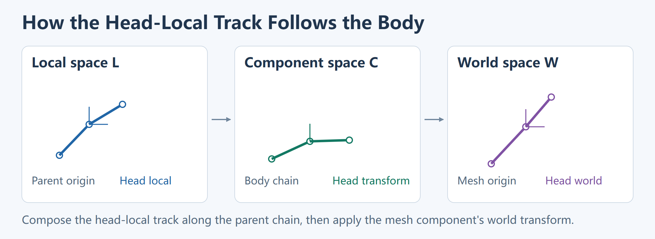
With column vectors, let L_i be the transform of bone i relative to its parent, C_i its component-space transform, and W_mesh the skeletal mesh component’s world transform.
C_i = C_parent(i) · L_i
W_i = W_mesh · C_i
The equations describe the spaces. At the UE call site, check the operator’s multiplication convention. A head-local track must be composed with the current body parent transform. World-space body and foot measurements must be reconciled with that same skeleton hierarchy. A space mismatch can look correct on a stationary pose and become visible as soon as the body moves.
Extracting Subtree-Local Transforms from an Existing Pose
The generator solves the body and legs, then saves local transforms for the head subtree. Descendants keep their local relationships when the head root changes. Restoring cached world transforms would instead leave them at their old world positions.
The script stores translation, quaternion rotation, and scale separately. For local position, subtract parent position, inverse-rotate the difference, and divide componentwise by parent scale. For local rotation, multiply the inverse parent quaternion by the child quaternion. Local scale is the componentwise ratio. To recompose, scale the local offset, rotate it with the parent, and add parent position. This is the script’s TRS convention and requires valid scale. General matrix shear is outside this model.
p_local = inverseRotate(q_parent, p_child − p_parent) / s_parent
q_local = inverse(q_parent) × q_child
p_child = p_parent + rotate(q_parent, s_parent × p_local)
q_child = q_parent × q_local
In 2D, place the parent at (100, 0) and the child at local offset (20, 0). Rotate the parent by 90° and the child should move to (100, 20). Skipping the parent rotation gives (120, 0) despite the correct local track value. In UE, a frame with a visibly rotated parent helps expose this before checking whether the pose write succeeded.
Head Quaternion Blending and Parent-Chain Reconstruction
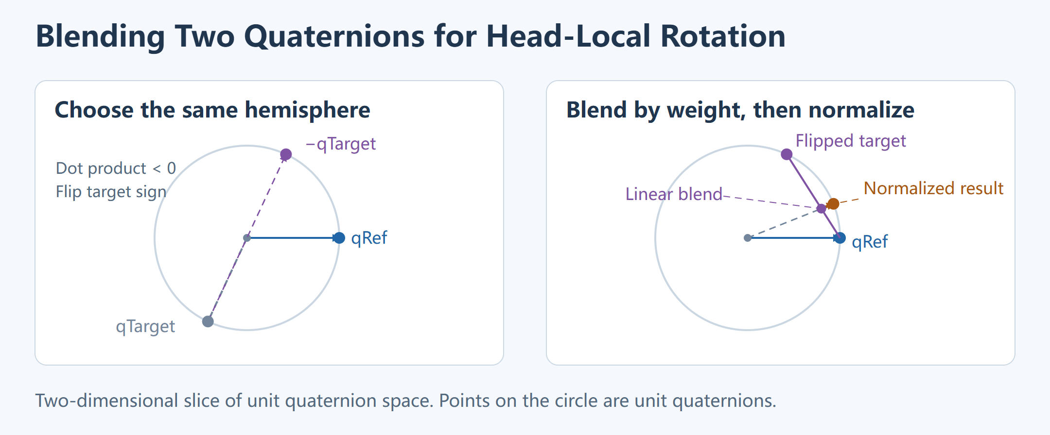
The reconstruction reads the head-local reference quaternion and converts the curve-driven target angles to a quaternion. If their dot product is negative, it negates the target to place both endpoints in the same hemisphere. It linearly blends the components and normalizes the result. This is normalized linear interpolation (nlerp) with hemisphere correction. Interpolation of the original asset’s rotation keys depends on its track and decoder.
if dot(qRef, qTarget) < 0:
    qTarget = −qTarget

qHead = normalize((1 − w) × qRef + w × qTarget)
Both q and −q represent the same rotation. Their uncorrected midpoint is zero and cannot be normalized. A negative dot product between less extreme endpoints can also produce an unnecessarily long path. Hemisphere correction selects equivalent endpoint representations. Normalization returns a unit quaternion. Compare shortest rotation angles so an equivalent sign flip does not register as a pose error.
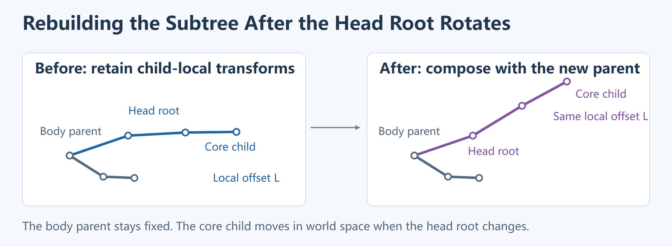
After replacing the head root’s local rotation, the script rebuilds the remaining bones as their parents become available. Each bone combines its saved local transform with the new parent transform. If the pending set is nonempty and no bone is ready, the script reports a hierarchy error.
Selecting the Override Subtree from Parent Indices
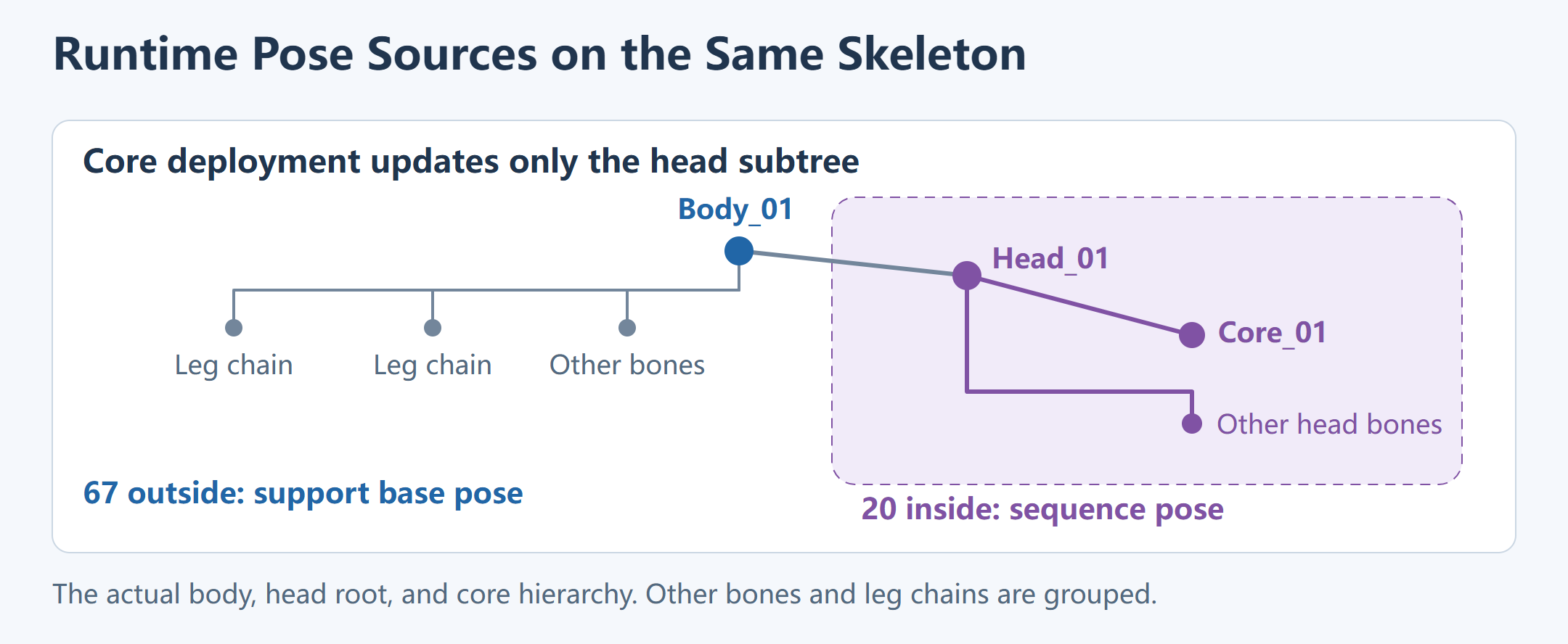
The body and legs supply the support base pose before the head root is updated. The parent chain defines the override. A core component can have an entirely different name and still belong to the head subtree. An accessory with a similar name can sit on a different branch and keep its existing pose. The script builds its lookup from the reference parent indices and walks up to the requested root.
A controlled test can use a head root, a core slider under it, and a body accessory that is a sibling of the head. Override the head rotation and the core should inherit it while preserving its offset. The sibling should retain its base pose. Add a local translation track to the core and the offset should follow the new head axes. Together these cases check inheritance, sibling exclusion, and animation on the descendant’s own track.
Pair the head transform with the body parent chain for the same frame. A frame-old asynchronous body pose can look correct while stationary and drift during turning or acceleration. Record action sample time, base pose sample ID, and the frame in which the pose was written. Hold frames show endpoints. Moving frames expose clock and parent-chain mismatches.
Single-Frame Solve Order for Curve-Driven Poses
The reconstruction evaluates curves at the current progress, computes blend weights, and updates the body transform. World-space support anchors constrain leg IK. The script then updates head-local rotation, rebuilds the head subtree, and checks leg rotation continuity and sole residuals.
progress, weight = sample_time_and_weight(frame, settings)
bodyCurve, bodyRotation, headRotation = evaluate_action(progress)
body = compose_body_target(bodyCurve, bodyRotation, weight, reference)

pose = solve_legs(body, fixedWorldAnchors)
pose = check_clearance_and_refine_continuity(pose, previousPose)
validate_joint_limits_and_self_collision(pose)

locals = extract_head_subtree_locals(pose, referenceParents)
locals[head].rotation = blend_head_rotation(referenceHead, headRotation, weight)
rebuild_head_subtree(pose, locals, referenceParents)

validate_frame_rotation_and_sole_positions(pose, previousPose, fixedWorldAnchors)
record_frame(pose, progress, weight)
Joint limits and same-leg self-collision are checked before the head override. Leg rotation differences and sole reconstruction errors are checked after rebuilding the subtree. If the rendered pose is wrong, reproduce the generator output first. Then compare UE readback to isolate target-bone and space errors.
Each frame records the pose, body target, action progress, blend weight, scaled source height, curve queries, head-local quaternion, and clearance and continuity results. A failure captures the first failing frame’s time, body orientation, ankle offset, and available joint deltas. The head-dip case applies this comparison to adjacent frames.
Head Subtree Before and After the Override
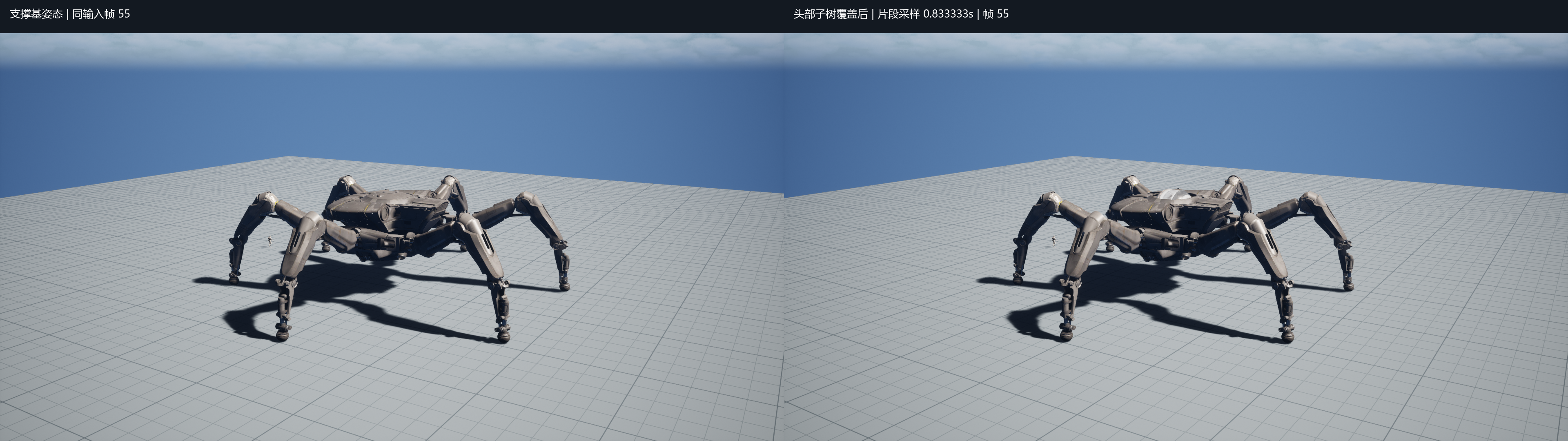
The capture compares the base pose and overridden pose at three sample points. Of the 87 reference bones, 20 fall inside the overridden subtree and 67 retain the current input pose. These counts apply to this skeleton and override boundary.
Head Dip: Curve Inputs and Head Rotation
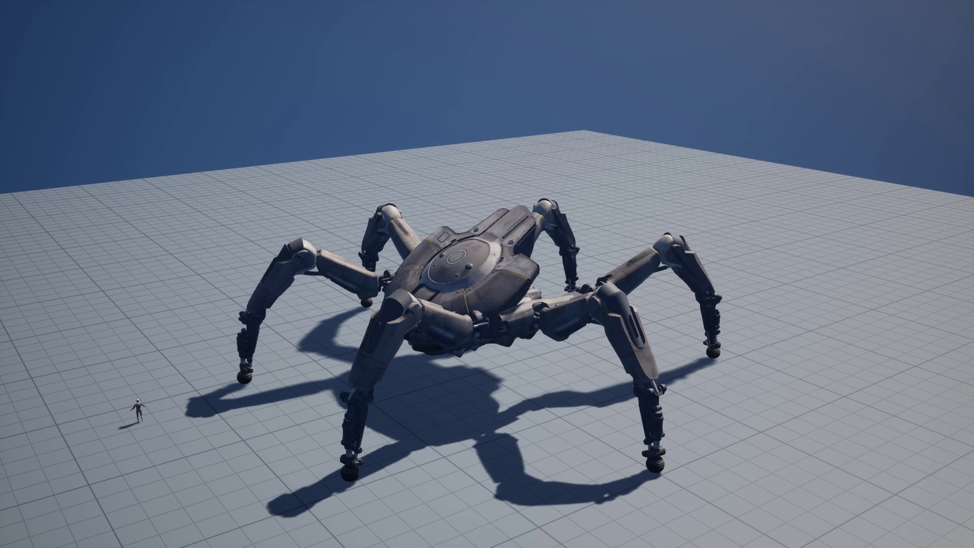
The head-dip demo retains source pose samples and recomputes head rotation with the recovered script. The action clock selects the curve sample. The head result is combined with the support base pose from the body and feet and written to the UE skeletal mesh component. The capture shows the pitch motion, and the per-frame record identifies the inputs that produced it.
The standalone video runs about 5.03 s at 30 fps. Its encoded length includes the recording setup. The original game trigger, springs, and mapping to the modular head Actor remain outside this experiment.

Pitch starts changing after about 1.0 s, reaches −30° at 2.0 s, and remains near −30° around 2.33 s before returning near the initial value. The plot uses video time. To explain which source keys or weights shaped each segment, inspect the source keys, playback phase, and head-script weights separately.
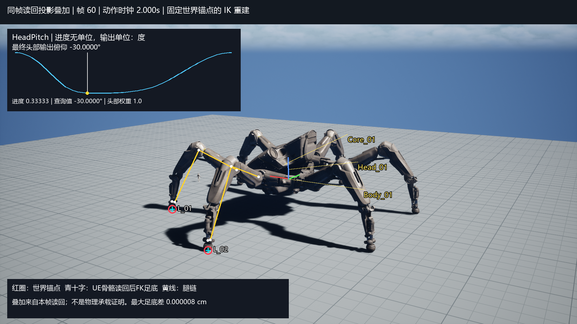
Curve Value, Blend Weight, and Pitch on Adjacent Frames
Before the −30° plateau, pitch moves from about −16.55° at 1.667 s on frame 50 to about −25.35° at 1.700 s on frame 51, a change of about 8.80°. This is a discrete change in the recorded head pitch channel. Source keys and the generator’s 5° leg-chain continuity limit measure different quantities.
| Frame | Normalized progress | HeadPitch query | Returned head blend weight | Output pitch |
|---|---|---|---|---|
| 50 | 0.222222 | -24.02277° | 0.695089 | -16.55299° |
| 51 | 0.233333 | -25.34952° | 1.000000 | -25.34952° |
The curve changes by about 1.33°, while head blend weight rises from roughly 0.695 to 1. The shortest rotation difference between the exported head-local quaternions is about 8.797°. The head blend-in flag turns off between these samples. The body branch has its own weight field. Separating the two effects on head pitch would require a replay that holds one input fixed.
Body Shake: Body Transform and Sole Constraints

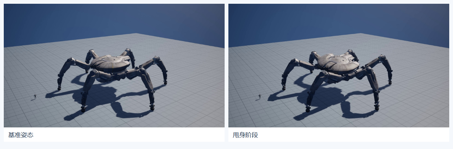
The body shake also uses action curves and recomputes head rotation. Turning the body root alone would take the legs with it and pull the feet away from their anchors. The local reconstruction re-solves leg IK at the new body transform while keeping the soles at their world-space anchors. The curve drives the body motion. The fixed-sole solve drives the leg adjustments.
The standalone capture runs about 5.73 s. The process video adds same-frame bone readback and reports the sole-to-anchor residual separately for the two recorded legs.
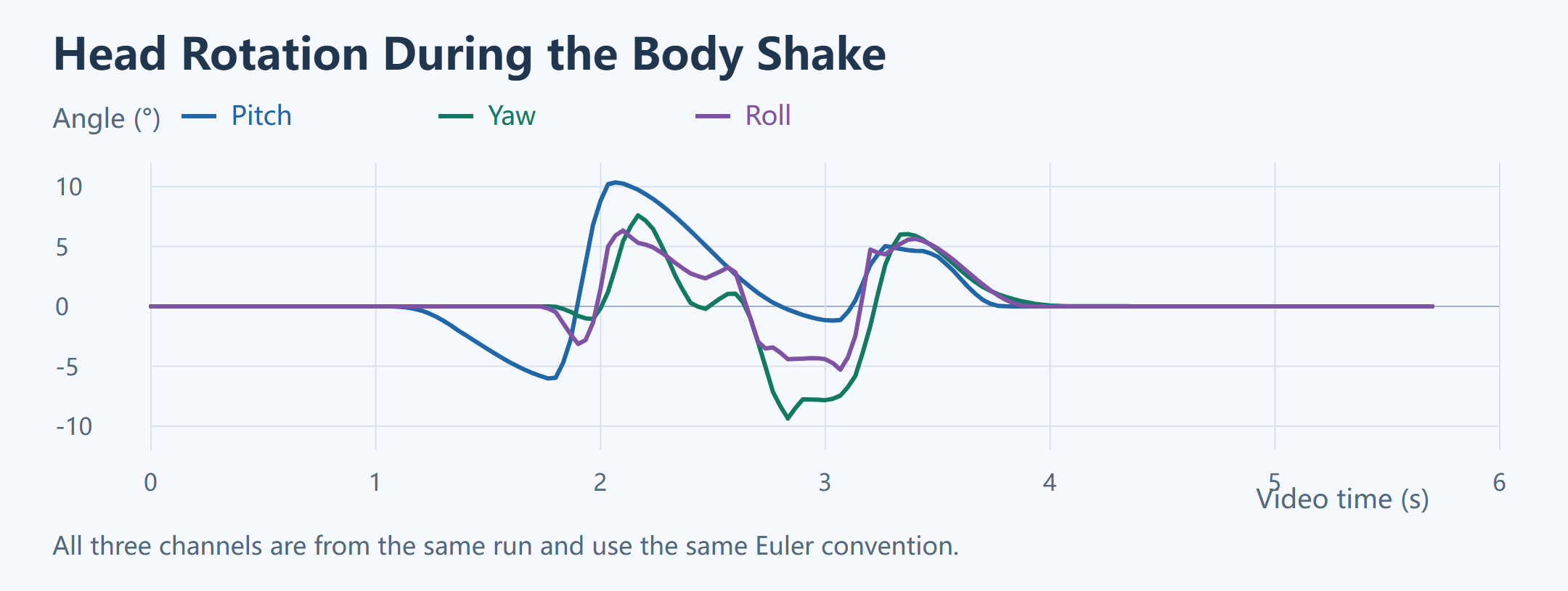
Head pitch reaches 10.35° at about 2.07 s, while yaw reaches −9.36° at about 2.83 s. These extrema occur in different samples. The three angle channels describe orientation and cannot be summed into a total rotation angle. To check for slip, pair each sample’s sole position and support state with the corresponding world-space anchor.
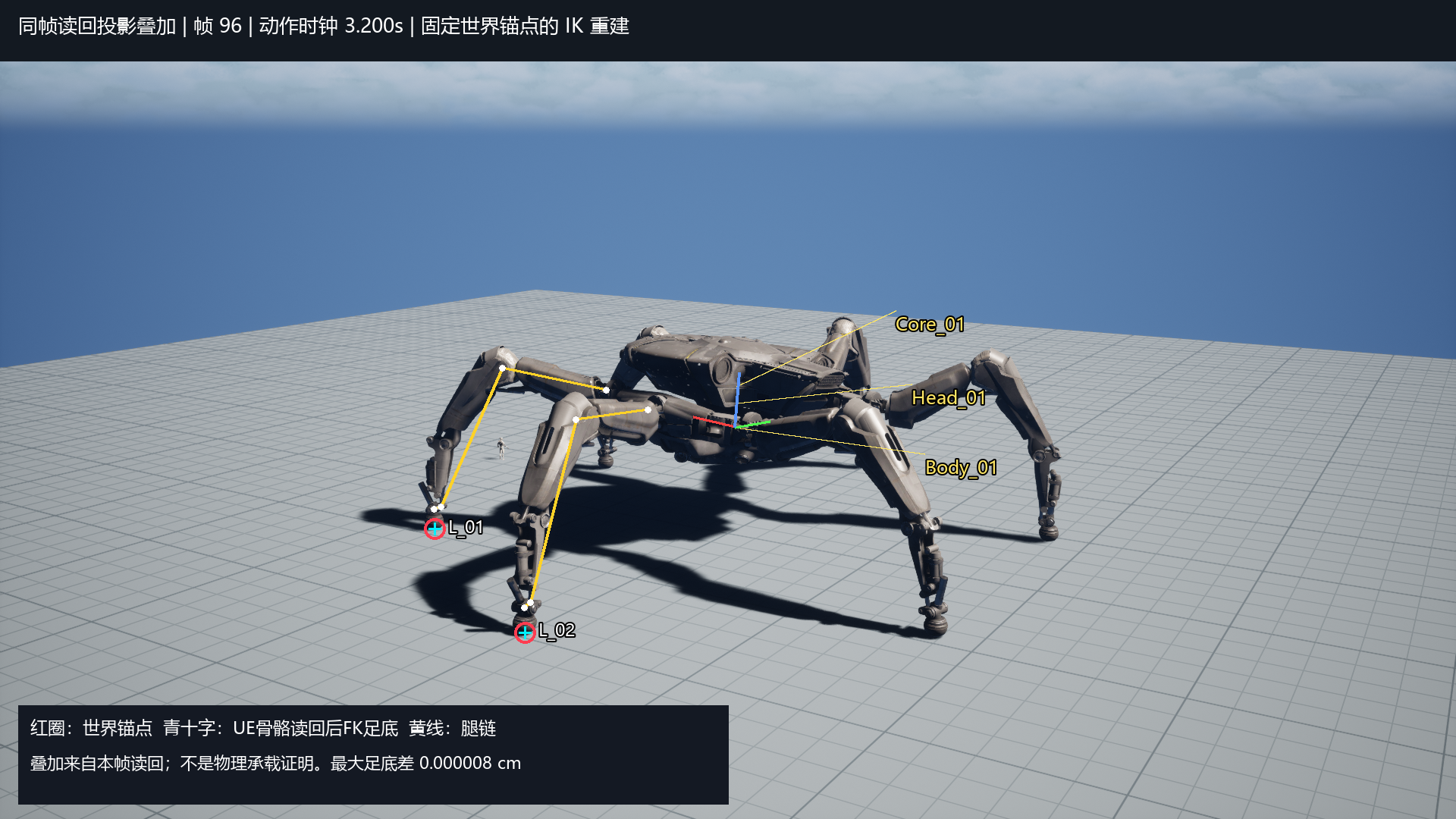
Leg IK with World-Space Sole Constraints
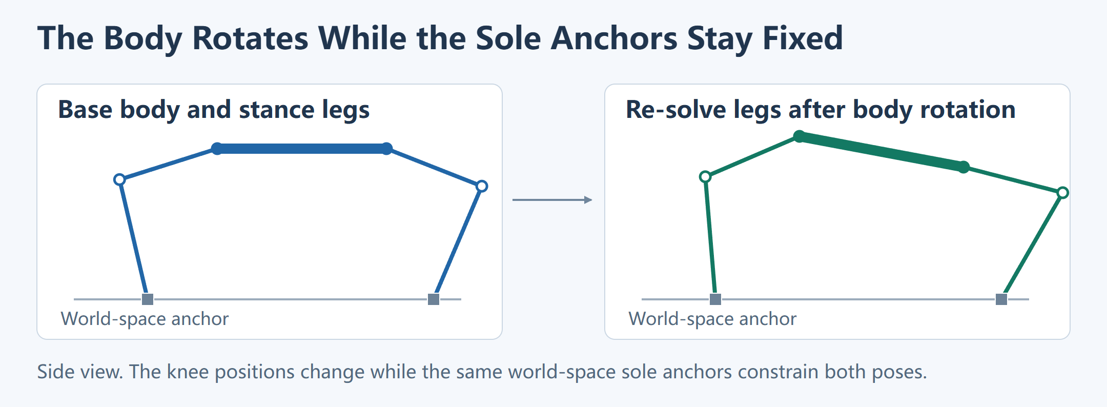
Before the action, the script constructs world anchors from the initial body position and nominal foot locations. Each sample updates body position and orientation, then reuses the same anchors as leg targets. The anchors fix the soles and IK determines how the knees and ankles follow. The script checks clearance, continuity, joint limits, and same-leg self-collision. This test checks whether a pose is feasible for a given body motion. The force controller in Part 1 reads foot positions after physics stepping.
Adjacent-sample rotation differences include body rotation. The script composes each sample’s body quaternion with its bone pose and compares the world orientations of the upper leg, lower leg, ankle, and foot on all six legs. Small component-space changes can still result in substantial world-space rotation. The rotations can also partially cancel. Record both spaces when diagnosing a large component-space change in a visually continuous leg.
The fixed-sole pose generator checks a 5° limit between adjacent orientations and uses FK to reconstruct the world-space sole, which must lie within 0.05 cm of the anchor. Several leg configurations can reach the same sole position, so a small residual can coexist with a discontinuous knee or ankle. On failure, the generator records the first failing frame, body pose, and joint deltas and stops. These limits apply to poses generated against fixed anchors. The predictive probe and the post-step IK solve in Part 1 have separate acceptance criteria. The pose in each video comes from that run’s own record.
Sole-to-Anchor Residuals
A sole position relative to the body can change as the body turns even when the sole stays fixed in world space. The residual is the difference between the sole reconstructed from the current body and bones and its world-space anchor. Keeping a vector for each foot helps distinguish a single-foot discrepancy from a shared axis error.
Head yaw and pitch extrema are separated by about 0.77 s. The process capture retains 172 samples each for L_01 and L_02. It pairs the world anchor with the sole reconstructed from UE bone readback after the pose write. The maximum position differences are approximately 5.13 × 10⁻⁶ cm and 4.23 × 10⁻⁶ cm, respectively. These are kinematic reconstruction residuals for two legs. Rigid-body contact and load require their own measurements.
Core Deployment: Sequence Sampling and Subtree Override
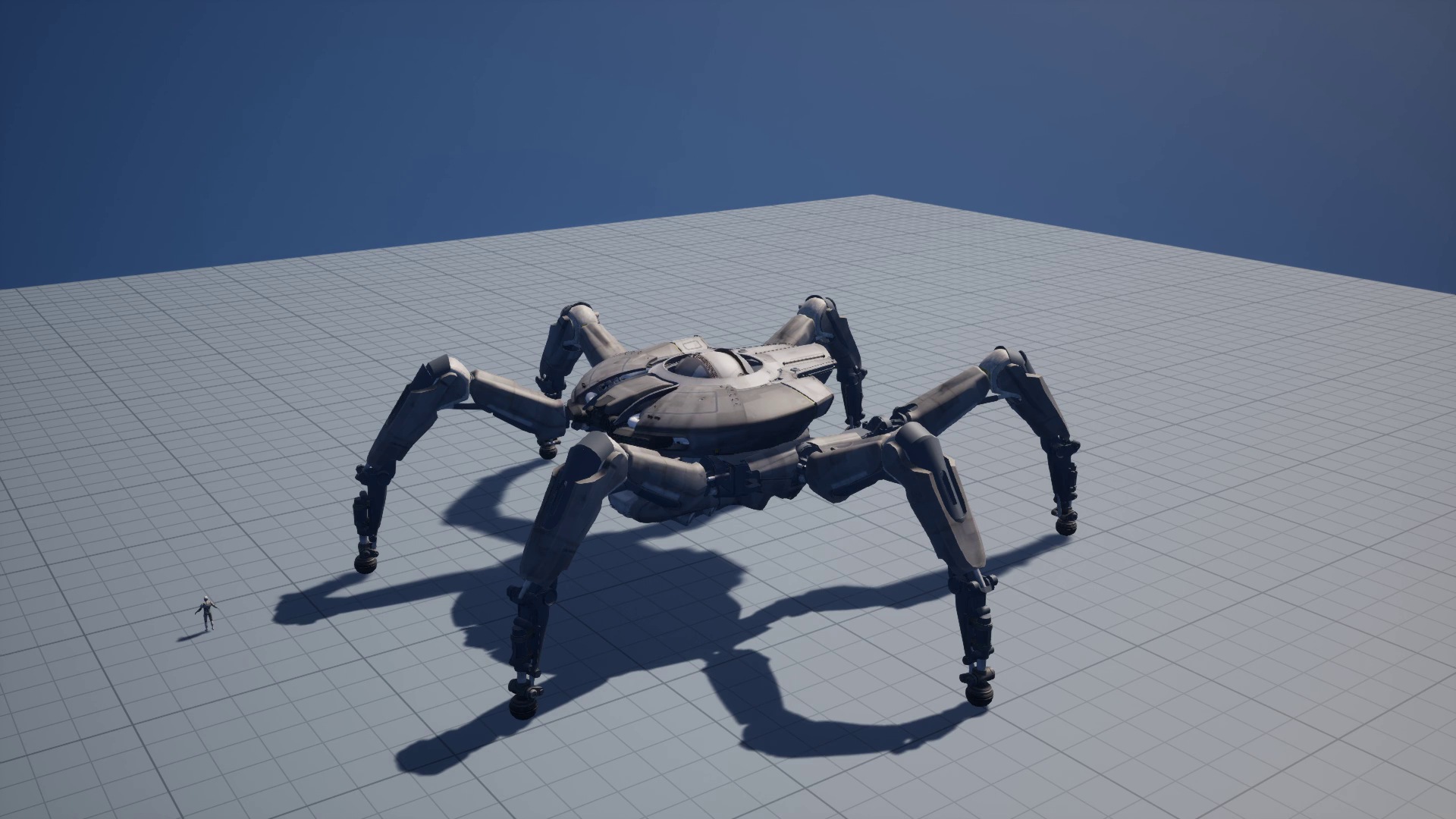
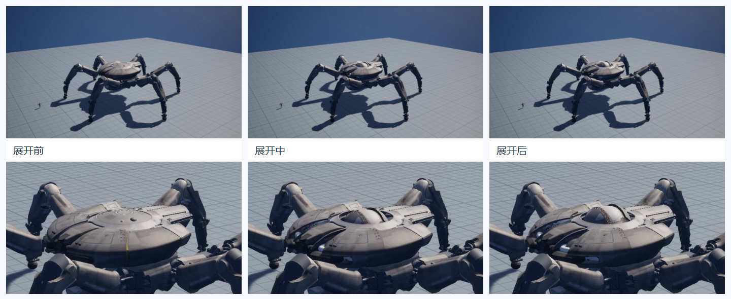
The imported A_Peppermint_01_OpenCore_02 animation sequence is about 1.667 s long. The test samples it into the head subtree while the body and six legs retain the support base pose. The capture holds both endpoints for about a second and encodes 111 frames at 30 fps, for a total of 3.70 s.
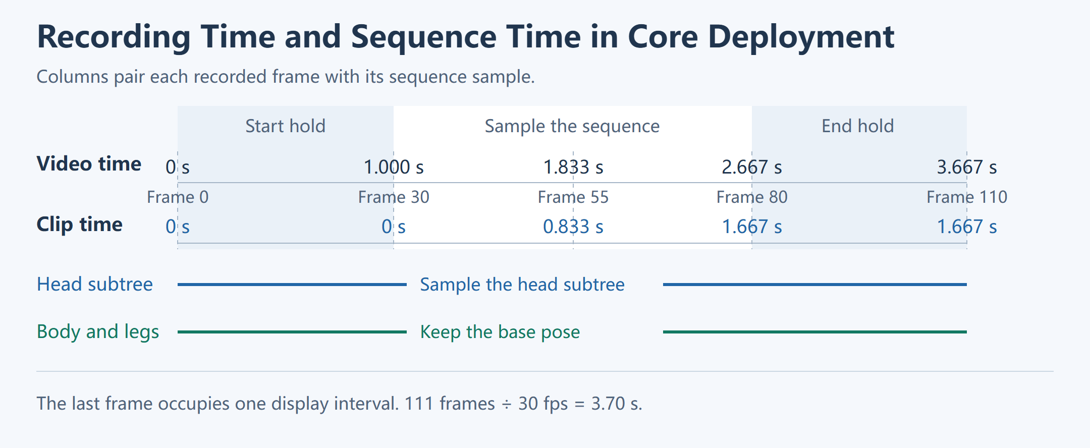
This test checks whether the imported tracks drive the intended subtree over time while preserving the outer body pose. Confirming the original binding between the Focus attack and core deployment requires the corresponding asset references and trigger records.
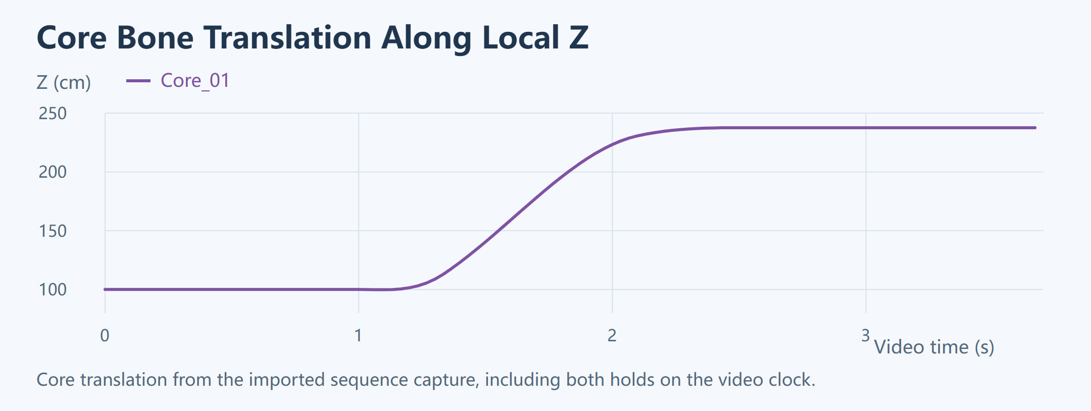
The record includes the frame number, sequence sample time, and core-bone translation. The initial hold samples time zero. At about 1.83 s on the recording clock, the sequence samples about 0.833 s. The final hold stays at the sequence endpoint. The recorded core Z rises from about 100.03 cm to 237.52 cm, a parent-local endpoint difference of 137.49 cm. The separately reported maximum translation change of about 137.53 cm uses a different statistic.
Head-root pitch, yaw, and roll stay close to the support base pose while the core bone translates locally. Check the actual target bone when validating a subtree override. The head-root angles alone miss the translation of Core_01.
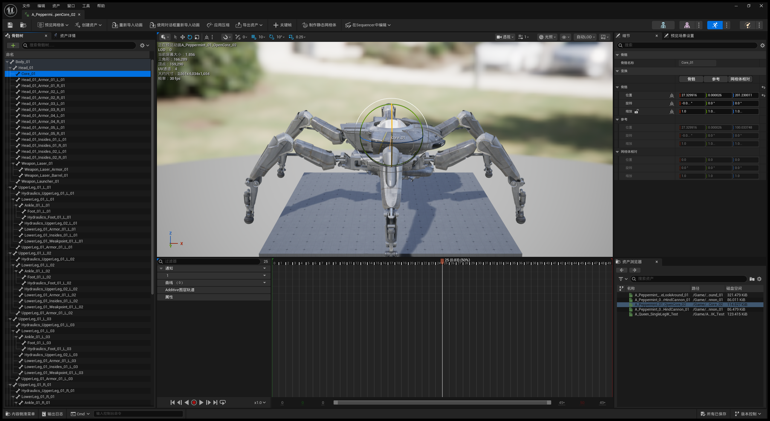
The process video shows actual editor windows sampled through the CLI, then switches to the runtime capture at normal speed and pauses at three comparison points. It labels frame sampling, pauses, and edits. The editor evaluates the complete asset pose. The runtime applies the sequence to the head subtree. Both paths are compared at the same sequence time in the core bone’s parent-local space.
| Sequence time (s) | Editor local Z (cm) | Runtime local Z (cm) | Local XYZ distance (cm) |
|---|---|---|---|
| 0.000 | 100.030243 | 100.033748 | 0.003505 |
| 0.833 | 201.230011 | 201.225571 | 0.004440 |
| 1.667 | 237.521347 | 237.520615 | 0.000732 |
The parent chain is Body_01 → Head_01 → Core_01. Z is the translation of Core_01 relative to Head_01. The XYZ distance compares positions in that same local space. All three distances are below 0.005 cm, with a maximum of about 0.00444 cm. The source of the discrepancy still needs to be isolated. The editor and runtime each provide their own pose outside the subtree.
Track Binding and Sampling Boundaries
An animation sequence supplies tracks bound to bones. Reproducing the import from source would require the decoder’s track mapping and checks for the bones and sample times used in UE. The records establish the local UE sample results. The complete compressed tracks, missing-track defaults, and full import trace remain to be verified.
For each bone, determine whether the track supplies an absolute local pose or an additive transform relative to the asset’s specified base. Compose an absolute pose along the parent chain. For additive data, apply the asset’s additive type and base reference. An absent track may retain the bone’s support base pose, while a rotation-only track still needs a translation and scale policy. The source records here do not establish a per-bone fallback policy. A regression can sample a complete track, a partial track, and a missing track at the same time and compare each result with UE.
In the 30 fps capture, frame 30 is one second into the video and still samples sequence time 0 s. Frame 80 reaches the sequence endpoint at about 1.667 s, then subsequent frames hold it. The recording time of frame 110 is 110 ÷ 30 ≈ 3.667 s. The sequence still samples at about 1.667 s. The final frame occupies one display interval, giving a total duration of 111 ÷ 30 = 3.70 s.
A read-only editor query matched all 87 model bone names to the reference skeleton by FName. The exported indices follow model-bone enumeration. The queried track index and bone-tree index both returned −1. Recovering the original compressed track indices requires a separate export from the compressed data. Verifying the missing-track policy requires a test sequence with a track deliberately removed.
Stomp Curves and the Force-Control Interface
The head dip and body shake use curves to reconstruct skeletal poses. Part 1’s section on stomp curve sampling and actuator targets introduces the same runtime path. The curves generate body and striking-foot targets. The controller tracks those targets through physics, then IK uses the measured sole positions to solve the skeletal pose. This section traces the curve fields, coordinate datums, and feed-forward terms that define those targets.
The main stomp action and its source recovery segment each last 2 s. The local adapter samples with clamp(t, 0, 4) / 2, so three seconds into the action corresponds to progress 1.5. Clamping to 1 at the input would skip the latter part of the curve. This interval belongs to the stomp adapter. The other demos use their own clocks.
The stomp adapter computes height from the current curve sample. Body Z target = initial striking-foot anchor height + BodyTZ × RefPoseBodyHeight. Accumulating the curve value frame by frame changes the trajectory. Adding the initial body height again raises the entire target and can put it beyond the stance legs’ reach.
The foot channels Towardness, Up, and Outness describe offsets relative to axes and action time. The body reference frame and foot anchor determine the resulting world position. Body height, foot offsets, and head angles each need their own unit convention even when all three come from floating-point curves.
Height Datums for Fixed-Sole Reconstruction and Stomp Control
RefPoseBodyHeight scales normalized body translation into local character units. Fixed-sole reconstruction uses the mean support-anchor height as the datum for its absolute Z target. The stomp adapter uses the same scale but takes the striking foot’s initial anchor as the Z datum, then passes the resulting target to the actuator. The difference becomes visible when the front foot and the other support feet start at different heights.
The stomp adapter takes the difference between current and initial body translation samples, scales it by the reference height, rotates it into the action heading, and adds it to the initial body position. It then overwrites Z with the striking-foot anchor height plus the scaled absolute curve Z. Rotation combines the initial orientation and the action-local rotation. The striking foot’s planar channels use a local scale of 150. The vertical channel is clamped to nonnegative values. The offset is rotated into the action heading and added to the foot anchor. The value 150 is an adapter parameter.
For example, an X channel starting at 0.10 and reaching 0.15 yields a 50 cm displacement with a 1,000 cm reference height. A 90° action heading rotates that displacement into the corresponding world direction. With curve Z = 0.9 and a striking-foot anchor at 40 cm, the absolute Z target is 940 cm. Taking adjacent-sample Z differences would produce relative motion. Adding initial body height again would shift the target upward and change the required leg reach.
Foot Velocity and Acceleration Feed-Forward
The stomp adapter sends a position target, velocity feed-forward, and acceleration feed-forward to the foot actuator. It samples foot targets on either side of the current time at the servo interval h. The interior uses a centered velocity estimate and second difference. Near action start, velocity uses the actual sampled time span and acceleration uses forward samples, avoiding negative-time queries.
v(t) ≈ (p(t + h) − p(t − h)) / (2h)
a(t) ≈ (p(t + h) − 2p(t) + p(t − h)) / h²
The servo integration comparison in Part 1 shows how derivative sampling and input hold affect the velocity increment per step. Here, h matches the servo interval for which the actuator holds the feed-forward input. A piecewise-linear position curve has constant velocity within a segment and a velocity change at a corner. Estimating acceleration over a much shorter interval than the servo step and holding it for the whole step makes the integrated velocity change sensitive to sampling phase. Even identical keyframe positions can yield different tracking. Check the derivative interval and the timing of the actuator write alongside p.
The adapter limits the feed-forward vector magnitudes to 3,900 cm/s and 49,000 cm/s². The actuator still combines them with position and velocity feedback and applies output limits. A sharp curve change by itself does not establish the rigid body’s acceleration. Part 1 records the target, physics readback, and braking correction at their respective stages.
Asset-Version Compatibility and Runtime Verification
Check the input version, field mapping, and object boundaries first. For an unknown type or unread bytes at the end of an object, record the asset, field, offset, and error. Then verify animation payload decoding, track mapping, coordinate conversion, and UE pose output. Check mesh LODs separately from animation tracks.
The version 2.01 records lack the original errors and per-track decode results for two failing objects. Keep container reads, field parsing, animation decode, and UE pose writes separate. If metadata reads successfully but the compressed payload cannot be expanded, the failure is in animation decode.
| Stage | Evidence to retain | Typical failure |
|---|---|---|
| Container read | Asset identity, version, and object boundaries | Truncated input or incorrect offsets and lengths |
| Field parsing | Resource references, types, and raw field values | Field mapping does not match the version |
| Animation decoding | Track time, bone identity, valid channels, and sampled values | Unsupported payload, wrong track binding, or incomplete missing-track behavior |
| UE pose write | Expected same-frame transform, component readback, and rendered pose | Parent-local to component-space conversion error or overwrite by a later layer |
Diagnosing Version Compatibility
Retain the input file, object ID, and offset at failure. A report that a file opens after a mapping change does not distinguish corrected field offsets from skipped payload. Compare the same object and track at the same sample time. Start with the boundaries and field values, then check track counts, bone identities, samples, and UE readback. If the parser can only read the name and duration, the evidence reaches the metadata layer.
If several tracks drift from the same frame onward, check segment time indices and compressed block boundaries. If only one bone moves the wrong part at the same time, inspect track-to-bone mapping first. To check missing-track behavior, sample with a support base pose that differs from the reference pose so the two possible fallbacks produce distinguishable results.
The three action captures show the resulting motion. The four process videos show how it was reconstructed or sampled. The head dip and body shake cover curve-driven output. Core deployment covers sequence timing and motion of the specified subtree. Animation events, attack binding, and gameplay triggers belong to Part 3. Version compatibility and the complete original animation graph need their own data and runtime records.
Track Mapping, Pose Composition, and UE Readback
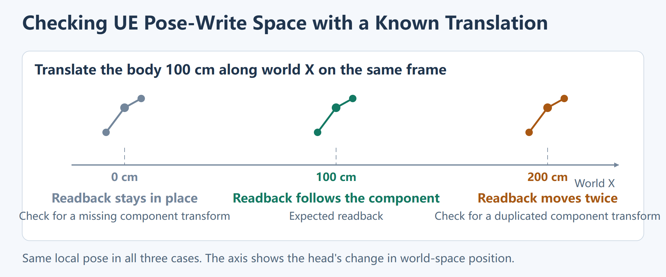
Align samples by asset time and retain the recording frame number separately. The source decoder and UE preview can sample at different rates. For action curves, substitute the action ID, channel, and curve value for the track fields, then continue from the generated local pose.
| Asset and clock | Track mapping | Local pose and parent chain | UE write and readback |
|---|---|---|---|
| Sequence or action ID, target skeleton, asset sample time, and recorded frame | Track index, source bone and parent, and valid channels | Target bone and parent, local TRS after missing-track handling, body pose, and support anchors | Expected component-space transform, value to write, target component and bone index, and transform read back after refresh |
Parent chain. Head tracks provide local transforms within the subtree. The rest comes from current body and leg input. If local quaternions match but component-space positions differ, inspect the parent hierarchy and skeletal mesh component space. Use the reference pose to check relative axes, then a rotated-body sample to check signs, axis swaps, parents, and override order. Core deployment preserves the body world transform, and the head and core still compose through the current chain. Compare core Z endpoints in the same space before interpreting the difference as extension along a part axis.
Pose-write interface. The host in Part 1 serializes the pose packet, calls QueenLivePoseLibrary.apply_world_pose, and checks the result. It uses the same entry point to restore the initial pose on reset. The records name RefreshBoneTransforms. The complete refresh order inside the core recorder still requires source verification. As a controlled test, move the body 100 cm along world X while preserving head-local pose. A world-space readback that stays put suggests a missing component transform. A 200 cm displacement suggests it was applied twice.
Readback. If the expected component-space transform is correct but refreshed readback differs, check the target component, bone name, and later overrides. If the parent updates while a child lags, reconstruct the child’s parent-local position from component transforms before and after refresh. For rotation, compare normalized qExpected and qRead for the same bone, frame, and space. The shortest angular difference is 2 × acos(clamp(abs(dot(qExpected, qRead)), 0, 1)) in radians. The head-pitch channel measures a different quantity. If the transform matches but the image still differs, check skin weights, LOD, and camera placement.
Units, Basis Changes, and Rotation Checks for Skeleton Migration
Confirm length units, basis axes, and rotation representation before scaling. If S changes coordinates from the source basis to the target basis, translation becomes scale × S × p and rotation becomes S × R × inverse(S). When S includes a reflection, arbitrarily reordering quaternion components gives no general conversion rule. Derive it from verified axis and handedness conventions, then test a bone with a known rotation and offset. The available evidence does not give a complete independently verifiable source-to-UE basis transform for core deployment.
Apply scale per field. An importer may convert the units of bone tracks while the action repository expresses body height relative to a reference height. Both can coexist if they apply to different inputs. Check whether the value is already in centimeters or has already been scaled by reference height. For a known local displacement, compare source, expected converted value, and final readback. A target skeleton with different bone lengths also needs its own reach and joint-limit checks.
Start with a single-axis rotation to confirm signs and axis mapping. Then rotate both parent and child to test composition order. Single-axis cases can hide multiplication-order errors. In compound poses, record normalized quaternions and compare the shortest angle in a specified space. Euler channels help describe the direction of motion, but subtracting their components cannot establish equivalence of arbitrary rotations.
Near an Euler singularity, a small rotation difference can produce a large change in the decomposed parameters. Quantization can introduce error on the return conversion. Compare normalized quaternions for the same input and target bone. The size of any Euler round-trip error still needs same-bone, same-frame readback.
Frame Samples and Error Statistics
A maximum error needs its comparison objects, space, units, and sample range. Comparing a generated pose with local bones measures reconstruction. Comparing decoder output with UE samples measures asset sampling. The plots here use timed head-rotation and core-translation samples. Other summary fields require verification of their calculation.
For the head dip, check the lowest pitch for amplitude and the start and end for blend windows and holds. For the body shake, inspect the pitch and yaw extrema separately to test the mapping at different body orientations. For core deployment, compare the start, middle, and endpoint of the same sequence to verify that the intended bone is updated across the interval.
Regression Checks for Curves and Animation Sequences
For repository curves, select an interior sample, a keyframe boundary, and a time outside the key range. With the input clock fixed, record the channel, adjacent keys, interpolation or extrapolation rule, and returned scalar. For a channel with no valid sample, record the caller’s fallback separately. The final pose alone cannot identify which query step caused a discrepancy.
For an imported animation sequence, retain the track mapping, local transforms, target parent, and refreshed component-space readback. The endpoints check duration and sampling boundaries. The interior checks decoding and the parent chain. Also test a body bone outside the override to verify that it retains the support base pose. A test that only checks whether the core moved can miss unintended writes elsewhere. Gameplay binding requires trigger, sequence-selection, and state-transition records.
From Sequence Sampling to Runtime Action Scheduling
The core deployment capture samples the sequence clock and adds holds around the action. An in-game attack request also depends on locomotion state, stability, and which system owns the action. Part 3 follows that handoff through the wait for stable support, execution, and release of ownership.