
For mid-to-senior engineers with an UE rendering background. The whole article uses, as a reference implementation, a runtime weapon-batching system shipped in a large FPS that has been live on mobile — walking through its overall flow, key technical choices, and implementation-level details: how to collapse a modular weapon assembled from a dozen parts into as few draw calls as possible at runtime.
Intro: why a single gun gets drawn a dozen times
Modern FPS weapons are almost always modular: a rifle is a barrel, upper/lower handguard, receiver, stock, magazine, grip, optic… a dozen independent SkeletalMesh parts, each mounted on a different socket of the weapon skeleton; swapping an attachment means swapping one of those parts. This structure is friendly to gameplay and to art workflow, but hostile to rendering:
- Component axis: every part is an independent
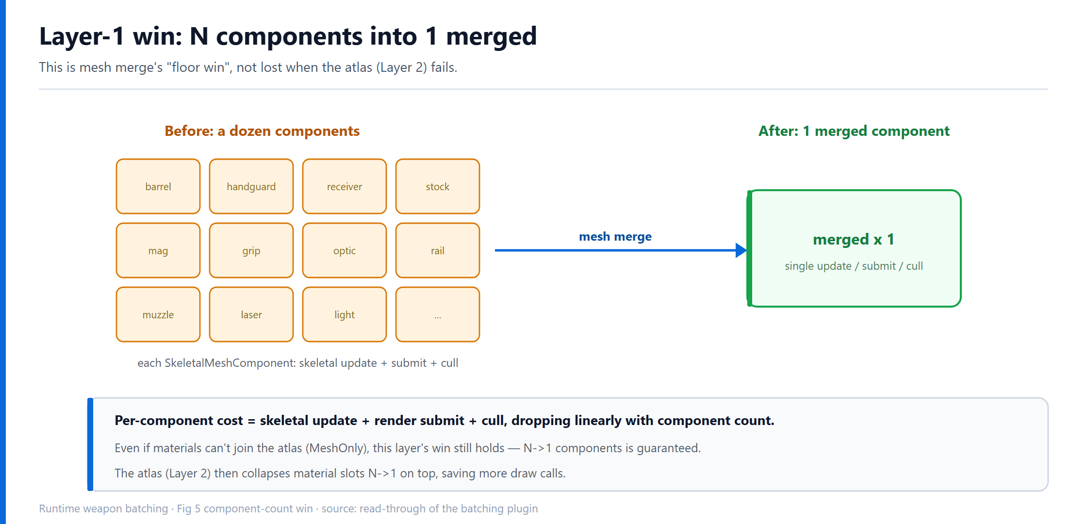
SkeletalMeshComponent, each doing its own skeletal pose evaluation and its own render submission. A dozen components means a dozen components’ worth of per-component cost. - Material axis: every part carries its own material, and every material is a Draw Call (written as *draw call* from here on). A gun with a dozen material slots is a dozen draw calls; put four or five teammates on screen, each holding one, and weapons alone eat over a hundred draw calls.
Mobile and low-end PC are extremely sensitive to draw-call count — that is the problem batching solves. And runtime weapon batching is not one thing; it is a two-layer stack:
- Mesh merge: merge the N part
SkeletalMeshes into a single merged mesh asset + a single component. The win is component count, skeletal update, and part of the draw-call count. - Texture atlas: on top of mesh merge, bake the N sets of textures into one atlas so the merged mesh’s N material slots collapse into 1. (Whenever this article says “1 draw call”, it means the material slot collapses into a single submission on the main render path; shadow / depth / velocity passes each count separately.)
The two layers stack, run on the same build pipeline, but fall back independently: if the atlas can’t be built, the mesh still merges. A stable batching system doesn’t chase a 100% success rate; it keeps *some* of the win under any combination of inputs — this “graceful degradation on failure” principle runs through the whole article, and is what makes it worth more than “how to call the MeshMerge API.” The article follows one main thread — “request a weapon merge → how the system builds it step by step” — to explain each layer’s flow, choices, and details.
One boundary up front: this is about a runtime dynamic weapon/equipment system — weapons need skeletal driving, free attachment combinations, and skin-driven material changes, so Nanite, static instancing (ISM/HISM), and GPU Scene (all aimed at static meshes) can’t replace this layer; Runtime Virtual Texture solves virtualization of huge-world textures, and also doesn’t solve the “material-slot and draw-call convergence” problem domain. The target here is always SkeletalMesh mesh merge and material convergence.

1. Overall architecture and flow: request, schedule, build state machine
Start with the global view. The system splits into three responsibilities:
Weapon logic (upper)              Batching subsystem                Build state machine
(WeaponModule)   --request-->   (MeshMergeSubsystem)  --drive-->   (MergeJob)
  "this gun wants batching"      priority queue / hash cache / pacing   Init->Load->Build->done
1.1 Request side: how a weapon enters batching
After assembling a modular weapon, the upper weapon logic submits an async merge request (RequestAsyncMerge) carrying: the weapon’s list of part SkeletalMeshes, per-part material override info, the target atlas size, and a key intent flag bWantMergeTexture (does this pass want the atlas too, or mesh-only).
The subsystem does three important things here — which is exactly why batching must go through a “subsystem + async” path rather than each gun merging itself:
- Hash cache and dedup: identically configured weapons compute the same mesh hash — the hash covers the part mesh list, socket config, material overrides, atlas size tier, and merge mode. The subsystem caches built merged meshes by hash, so identically configured weapons reuse directly and never re-merge; with many players on the same map, or many players using the same gun, the savings dwarf the cost of batching itself. Identical-hash requests arriving in the same frame are also coalesced onto the same build handle, so two copies aren’t built at once. (Changing skin = the material override changed → different hash → a fresh merge, never reusing a stale atlas.) The cache can’t only grow: real projects pair it with resource lifetime management — refcounting, LRU eviction, or cleanup on level unload — or the merged-resource cache grows without bound.
- Priority queue: your own weapon (first-person) has the highest priority; teammates’ and distant ones drop off from there.
- Pacing: atlas drawing costs GPU/main-thread time, so the subsystem uses a per-frame cap (
WeaponMerge.MaxAtlasPerFrame) to spread builds over multiple frames, avoiding a hitch when a dozen guns pour in at once.

1.2 Build side: a state-machine object
Each actual build is carried by a build object (call it MergeJob), internally a state machine that advances one state per Tick, switching states via SetState(new next-state), with SetState(nullptr) meaning the whole build is done. The flow:
Init --> LoadSkeletalMesh --> [LoadOverrideMaterial] --> Build --> done (SetState null)- Init: initialize, validate the request.
- LoadSkeletalMesh: async-load all part
SkeletalMeshes into memory (some may not be loaded yet). - LoadOverrideMaterial: if the request carried override materials (skins, etc.), async-load those too; otherwise skip straight to Build.
- Build: where the real work happens — merge skeleton, merge mesh, build atlas, bind materials, finalize. Nine-tenths of this article is about what happens inside this state.
Making the build a state machine rather than one big function is fundamentally because it spans multiple frames, and every step may be waiting on an async result (resource load, texture streaming, RHI init). The state machine turns “waiting” into a natural Tick return — come back next frame — with no thread blocking and no callback hell.

1.3 The top-level branch of Build: WeaponMerge.AtlasMode decides how far it goes
Inside Build, the first fork is the global switch WeaponMerge.AtlasMode:
Mode == 0: mesh-only. Build the merged mesh directly, each part keeps its own material slot — take the component-count win, skip the atlas.Mode == 2: mesh + GPU atlas. Run mergeability analysis first, then draw the atlas, then build the mesh, and finally bind the atlas back into materials. (Mode == 1is a historical CPU-atlas path whose runtime cost is unacceptable; the stub is kept but disabled.)
The skeleton of Build’s Tick:
void FMergeState_Build::Tick(FMergeJob* Setup)
{
    if (CVarAtlasMode.GetValueOnAnyThread() == 0)
    {
        // mesh-only: build -> async build finished -> finalize
        if (BuildMesh(Setup) && Setup->MergedSkeletalMesh->IsAsyncBuildFinished())
            ActiveStopBuildStateIfBuildSuccess(Setup);
        return;
    }

    // atlas: analyze mergeability first, branch on the three-state result
    EMergeResult Result = AnalyzeMergeability(Setup);
    switch (Result)
    {
    case EMergeResult::Unmergeable:        // can't merge at all
        ActiveStopBuildStateIfBuildFailed(Setup);
        break;
    case EMergeResult::Atlas:              // atlas is possible
        DrawAtlasTextures(Setup);          // draw the atlas
        if (IsAtlasReady(Setup) && BuildMesh(Setup)
            && Setup->MergedSkeletalMesh->IsAsyncBuildFinished())
            ActiveStopBuildStateIfBuildSuccess(Setup);
        break;
    case EMergeResult::MeshOnly:           // atlas impossible, but mesh mergeable
        if (BuildMesh(Setup) && Setup->MergedSkeletalMesh->IsAsyncBuildFinished())
            ActiveStopBuildStateIfBuildSuccess(Setup);
        break;
    }
}
Note one design-critical point: the analysis result is three-state, not a “mergeable / not” boolean. MeshOnly means “the atlas can’t be built, but the mesh still merges” — this is where the layered fallback from the intro lands in code. Section 5 is dedicated to this three-state.
2. Layer 1: mesh merge
The goal of mesh merge: merge the N part SkeletalMeshes into a single merged mesh asset (call it MergedSkeletalMesh), mounted on a single component. It handles four things: skeleton, sockets, bone mapping, render data.
2.1 Skeleton merge
Each of the N parts has its own RefSkeleton. The merged mesh needs one skeleton that can drive all parts’ vertices, so the N skeletons merge into one. The system offers two paths:
- Normal merge: take the weapon’s main skeleton as the base and fill in the bones missing from each part’s skeleton, dedup by name.
- Custom merge: the upper layer explicitly provides a target skeleton, and each part maps into it. Used where assembly is complex and precise bone ordering is required.
One product of the merge is the source→target bone map (BuildSrcToDestBoneMap): part A’s 3rd bone corresponds to which bone in the merged skeleton. This table is the basis for later moving vertex skin weights — a vertex’s bone indices must be remapped from “part-local” to “merged-skeleton-global”.

2.2 Socket merge
Weapon mount points (optic slot, muzzle, magazine slot…) exist as sockets on each part’s skeleton. After merging they must migrate onto the merged skeleton with their relative transforms preserved, or the optic sits crooked and the muzzle flash drifts. The custom and normal paths each have their own socket-migration logic (AddCustomSocket / AddNormalSocket).
2.3 Render-data merge
This is the heavy part of mesh merge: merging each part’s per-LOD vertex buffer, index buffer, skin weights, and section info into a single LOD render data for the merged mesh. Key points:
- Vertex copy: for each part, copy positions, normals/tangents, UVs, and skin weights into the merged buffer, rewriting skin bone indices via the map from 2.1.
- Section merge: each part’s each section (a run of triangles sharing one material) flows into the merged mesh. The merged mesh’s sections carry a mapping table recording “which part this section came from, and whether it uses the merged material or the original” — that table is the seam between Layer 1 and Layer 2, detailed in Section 6.
- Per-LOD handling: the merge must align LODs. The system takes the minimum LOD count across parts as the merged mesh’s LOD count and merges level by level. This is why mergeability analysis has a hard check that “all parts’ LOD counts must match” — if LOD counts don’t align, section mapping can’t propagate across levels.
2.4 Why mesh merge is its own layer
A natural question: since the end goal is to collapse into 1 draw call via the atlas, why not make mesh merge and atlas merge one thing?
Because their success conditions differ, and mesh merge’s is far looser. The atlas requires parts’ materials to be highly homogeneous (next section), and in reality a gun always has a few “outlier” parts (a procedurally generated lens, a special-material tactical light) that can’t join the atlas. If the two layers were coupled, one outlier part would kick the whole gun back to “not merged at all.”
With layering: outlier parts drop the atlas to MeshOnly, but the mesh still merges — component count goes from a dozen to 1, skeletal updates coalesce, and most sections still ride the merged mesh. Layer 1’s win is the “floor win,” never lost because Layer 2 failed. This is the bedrock of the whole system’s robustness.
3. Layer 2: choosing the atlas technique
After mesh merge, the merged mesh still carries N material slots. To collapse them into 1, bake the N sets of textures into one atlas so all sections point at the same base material. The core technical-choice question is: how is the atlas baked?
3.1 Weighing three routes
Route A: CPU per-pixel copy. Decode each source texture into a pixel array on the CPU, copy it into the corresponding region of one big image by layout, then upload as a single texture.
- Pro: straightforward, platform-agnostic.
- Fatal con: runtime textures are various GPU-compressed formats (BC/ASTC…) that must be decoded on the CPU first; big-image copies are pure CPU-bound work that stalls the main thread; and you handle mips yourself. Untenable at runtime (especially on mobile). Rejected.
Route B: an engine-customized GPU merge-texture class. Some projects build a customized “mergeable texture” type in the engine, extending the underlying texture resource privately, and pair it with runtime compression (RTC) to produce a compressed merged texture directly.
- Pro: the output is a compressed texture, VRAM-friendly, ideal on mobile.
- Con: heavy coupling to private engine changes. That custom type and its RTC dependency chain are a whole engine-level modification — expensive to maintain, port, and upgrade, and tightly bound to the upper layer. As a “general, reusable” solution it’s too heavy.
**Route C: UTextureRenderTarget2D + Canvas drawing (chosen).** Create a RenderTarget and use the engine’s Canvas API to draw each source texture into it by layout, then sample it directly as the atlas.
- Pro: pure upper-layer API, no engine-core changes.
BeginDrawCanvasToRenderTarget+K2_DrawTextureare public interfaces; drawing is submitted on the render thread and executed by the GPU pipeline, source-texture decode is handled by the sampling hardware (no CPU decode), the implementation is light, portable, and maintainable. (It still depends on the RenderThread, RHI, and RenderTarget lifetime — it just doesn’t touch engine core.) - Cost: the RT is uncompressed, so its VRAM cost is bigger than Route B. RenderTarget goes through the runtime-resource path and does not pass through the offline texture-compression pipeline, so it gets no BC/ASTC compression win — that is precisely its key difference from a regular
UTexture2D. This is its main trade-off; Section 11 does the math.
Choosing C trades “implementation cost / maintainability” against “VRAM cost” for PC and the dev cycle: PC VRAM is relatively roomy, so swapping a whole engine-modification maintenance burden for an uncompressed RT is worth it; if VRAM is tight when shipping on mobile, you stack RTC compression on top of C, but that is a separate link that doesn’t affect the main chain.

Why not the other “batch-texture” approaches? Advanced readers will think of Texture Array, Runtime Virtual Texture, and Bindless — they solve different problems: the atlas solves spatial organization (pack many into one), VT solves texture residency (load huge textures on demand), Texture Array solves the sampling set (sample many layers at once), Bindless solves binding count (break the slot limit). They can be combined with the atlas, but none replaces “collapse the material slots into one” — which is exactly the atlas’s job in this chain.
3.2 The full data flow of atlas merge
With RT + Canvas chosen, the pipeline from “a weapon’s part materials” to “a single base material + one atlas” is:
1) Mergeability analysis  AnalyzeMergeability
   - find the base material (majority)
   - group source textures by material param name (BaseColor / Normal / ...)
   - decide the three states
2) Packing               PackAtlas
   - compute each source texture's normalized position + scale in the atlas -> AtlasTransforms
3) UV bake               BakeSectionMapping
   - bake the transform into merged vertex UVs; sections point at base material or original
4) Atlas draw            DrawAtlasTextures
   - one RT per group; Canvas draws them in one by one; generate mips explicitly
5) Material bind         BindAtlasTextures
   - bind the drawn atlas back into the base-material MID by param name
The next five sections take these five steps apart one by one.

4. Mergeability analysis: three-state design and the base material
Whether the atlas can be built depends on whether the parts’ materials are “alike enough.” Mergeability analysis (AnalyzeMergeability) answers that and prepares data for the later steps. Its output is a three-state enum:
enum class EMergeResult
{
    Unmergeable,   // can't even merge the mesh (invalid data)
    MeshOnly,      // atlas impossible, but mesh mergeable (safety path)
    Atlas,         // atlas possible (best path)
};
4.1 Why three states
With only a “mergeable / not” boolean, “atlas failed” could only fall back to “merge nothing,” losing all of Layer 1’s win. Three states decouple “can the mesh merge” from “can the atlas merge”:
Unmergeable: the input itself is invalid (no parts, mismatched LOD counts); the mesh can’t merge either, so fail outright.MeshOnly: the mesh merges, the atlas doesn’t. Take mesh merge, each section keeps its original material. This is the safety path, and the state that best shows the value of layering.Atlas: materials are homogeneous enough, the atlas builds, run both layers.
In code, nearly every “atlas can’t be built” criterion lands on MeshOnly, not Unmergeable — the analyzer’s default bias is “hold on to mesh merge as much as possible.”

4.2 Gathering material info
The first step flattens and gathers material info across all parts, all LODs, all sections (ExtractMeshLODSectionsMaterialInfo). For each section it resolves the material actually used — a three-level priority:
- an override material carried in the request (a skin, etc.) wins;
- otherwise the material index redirected by the LOD info’s
LODMaterialMap; - once the material interface is in hand, walk up to its parent material as the “base material” — because two parts may use different instances (MIs) of the same material, with different params but the same parent; judging homogeneity looks at the parent.
4.3 Finding the base material: the majority rule
A weapon’s dozen sections don’t necessarily all use the same material. The atlas needs one “base material” that all merged sections share. The rule is majority (PickBaseMaterial): count how often each base material appears across all sections; the most frequent one becomes the base material.
TMap<UMaterialInterface*, int> MaterialsCntMap;
// iterate all sections, counting each section's base material...
UMaterialInterface* RefMaterial = nullptr;
int RefBaseMaterialCnt = 0;
for (auto& Element : MaterialsCntMap)
    if (Element.Value > RefBaseMaterialCnt)   // take the most frequent
    { RefMaterial = Element.Key; RefBaseMaterialCnt = Element.Value; }
Majority rather than “must all match” is another design leaning toward “merge as much as possible”: majority sections go into the atlas via the base material, and the few outliers fall back to their originals (shown as SectionID = -1 in Section 6).
After picking the base material, among the sections using it, pick the material instance with the most texture params as the “param template” (BaseRefMaterialInstance) — it decides “which texture params this material set actually has to merge.” If even this can’t be found, drop straight to MeshOnly.
4.4 Group by param name, force BaseColor to group 0
A material has several textures: BaseColor, Normal, Roughness/Metallic/AO (often packed into one NR or MAC)… The atlas doesn’t mix all textures into one; it bakes one atlas per texture class, by material param name: all parts’ BaseColors into one BaseColor atlas, all Normals into one Normal atlas, and so on. So each of the base material’s texture params maps to one atlas RT.
In code this is expressed as “category groups”: each group binds a material param (e.g. BaseColorMap) and holds all parts’ textures of that class.
Here’s a small but critical detail — BaseColorMap is forced to group 0:
if (MaterialParameterInfo.Name == TEXT("BaseColorMap"))
    TexturesParameterInfo.Insert(MaterialParameterInfo, 0);   // insert at front
else
    TexturesParameterInfo.Add(MaterialParameterInfo);
Why? Because packing and size adjustment use group 0 as the reference. All category groups share one atlas layout (BaseColor in the atlas’s top-left → the same part in the Normal atlas is also top-left); the layout is computed once, using group 0’s texture sizes. BaseColor is usually the best proxy for “how big this part should be,” so it’s the most sensible reference. All groups’ slot counts and layouts must match exactly, or UV transforms cross-wire — there’s a dedicated bit of code that pads groups to “the same slots for every group.”
4.5 The fallback gates, one by one
By this point the analysis hits a series of gates; failing any one drops it to MeshOnly:
- No base material instance → no way to determine texture params.
- **No mergeable texture-param groups, or
bWantMergeTexture == false** → the upper layer didn’t want the atlas this pass (e.g. the first-person near-view quality split, Section 11). - Mergeable source textures ≤ 1 → with only one texture, an atlas is pointless (the atlas exists to pack several together).
- Packing failed → doesn’t fit (Section 5).
Only passing all yields Atlas. Whichever branch it takes, at the end it always calls BakeSectionMapping to do the section mapping and UV baking (Section 6) — because even mesh-only needs the section→material mapping.
4.6 Propagate LOD0’s conclusion to other LODs
Analysis runs only on LOD0 (BaseLODIndex = 0), deciding “which section uses which atlas texture.” Other LODs aren’t re-analyzed; instead, matched by material interface, LOD0’s merge conclusion is copied over: if a section in LOD1 uses the same material interface as some section in LOD0, it inherits that section’s atlas index and “participates in merge” flag. This keeps the same part’s atlas mapping consistent across all LODs and skips per-LOD re-analysis.
5. Packing: fitting differently sized textures into one atlas
Analysis decided “which textures to merge”; packing (PackAtlas) decides “which region and what size each texture takes in the atlas.” The output is, per source texture, one normalized transform FVector4(ScaleX, ScaleY, CoordX, CoordY) — scale and top-left coordinate, all normalized to [0,1].
5.1 First, does the area fit
The atlas is a fixed-edge square (TargetMergeTextureSizeX, 2048/1024 by view tier). Packing first checks total area:
uint32 TargetArea = TargetSize * TargetSize;             // atlas total area
uint32 TextureTotalArea = Sum(each source SizeX * SizeX); // sum of source areas
If TextureTotalArea <= TargetArea, great, place them directly. If not, shrink some source textures — the most interesting part of packing.
5.2 The two-stage halving strategy
Shrinking isn’t a blind uniform scale; it’s two stages, minimizing quality loss:
Stage 1: bring “over-spec” textures back to default first. Each texture has a “config default size” (the sensible size art set for that part) and a “reduce-priority order” (ReduceTextureSizeOrder, which textures may be sacrificed first). Stage 1, by priority order, halves each texture whose current size is above its default, until enough space frees up. This cuts “over-spec” redundancy with almost no perceptual loss.
if (TextureTotalArea > TargetArea)
{
    InTexReduceSize.Sort(CompareReduceOrder);   // sort by reduce priority
    int32 SpaceArea = TextureTotalArea - TargetArea;
    // Stage 1: only shrink textures whose current size > config default
    for (...; SpaceArea > 0; ...)
        if (tex.SizeX > tex.DefaultSizeX && tex.DefaultSizeX > 0)
        {
            uint32 Reduced = tex.SizeX / 2;
            SpaceArea -= (tex.SizeX*tex.SizeX - Reduced*Reduced);
            tex.SizeX = Reduced;  tex.MipIndex++;
        }
    ...
}
Stage 2: still doesn’t fit, halve everyone in turn. If cutting over-spec isn’t enough, enter a “sort largest-to-smallest, then halve everyone in turn” loop until it fits (with a trycnt < 100 infinite-loop guard). This starts costing real quality, but by shrinking the largest first, the perceptual loss stays contained.
Halving rather than an arbitrary ratio is because halving maps exactly to dropping one mip level — the source texture’s ready-made next-lower mip *is* its halved result, free to use, no re-sampling. Each halving does MipIndex++, recording “which mip level of this texture to take.”

5.3 Placement and normalized transform
With sizes set, a rectangle packer (FAtlasPacker, internally the classic largest-first placement + space split) computes each texture’s top-left offset. Finally, “size + offset” normalizes into a transform:
float ScaleX = (float)AdjustSizeX / TargetSize;   // fraction of atlas width
float ScaleY = (float)AdjustSizeX / TargetSize;
float CoordX = (float)Offset.width  / TargetSize; // normalized top-left x
float CoordY = (float)Offset.height / TargetSize; // normalized top-left y
AtlasTransforms.Add(FVector4(ScaleX, ScaleY, CoordX, CoordY));
This FVector4 is packing’s final product, fed to two places at once: drawing decides which region of the RT the texture goes into (Section 7); UV baking decides how the original vertex UVs map into the atlas (Section 6). One piece of data, two consumers — a clean part of the design.
6. UV baking and section remapping
Once the atlas is drawn, sampling must hit the right region: part A’s UVs were [0,1] relative to its own 512 texture, but that texture now sits in some 512×512 region of the top-left of a 2048 atlas, so sample coordinates must scale and translate accordingly. Two ways:
- Change the sampling logic in the material: pass each section a set of UV-transform params and transform-then-sample in the material. Downside: the base material must add params and instructions for this, and per-section params mean it can’t really collapse to one draw call.
- Bake the transform into vertex UVs (chosen): pre-transform each vertex’s UVs and write them into the merged mesh’s vertex data. The material reads UVs that are already atlas coordinates, the sampling logic is unchanged, and all sections share the exact same base material → a real single draw call.
The latter is chosen. Baking happens in BakeSectionMapping, which does two things at once: produce the UV transform + build the section→material mapping.
6.1 UV transform: from normalized transform to vertex transform
For each part’s each LOD’s each section, if it participates in atlas merge (bUsedForMerging), build a UV transform from packing’s FVector4:
if (bUsedForMerging)
{
    LODMapping.SectionIDs.Add(0);          // points at merged material (base MID)
    FVector Scale = FVector(Transform.X, Transform.Y, 1.0f);       // ScaleX, ScaleY
    FVector Translation = FVector(Transform.Z, Transform.W, 1.0f); // CoordX, CoordY
    SectionUVTransform.Add(FTransform(FRotator::ZeroRotator, Translation, Scale));
}
This FTransform applies to every vertex’s UV of that section during render-data merge: newUV = oldUV * Scale + Translation. The old [0,1] UVs are squeezed into that normalized region of the atlas.
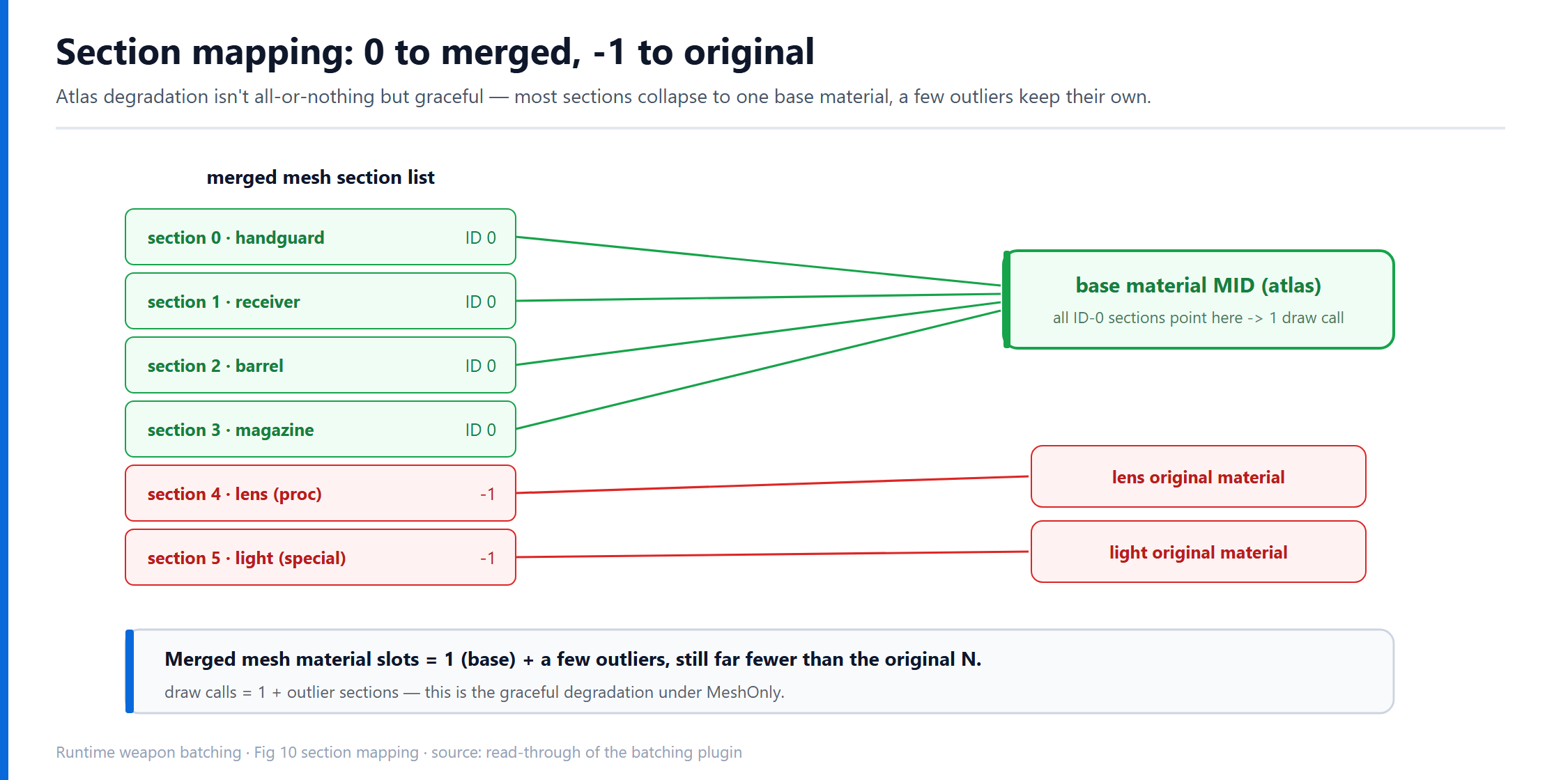
6.2 Section mapping: 0 goes to merged, -1 goes to original
Note the SectionIDs.Add(0) above — 0 means “this section uses the merged material (the one base MID).” Outlier sections that can’t join the atlas take the else branch:
else
{
    LODMapping.SectionIDs.Add(-1);   // -1: not the merged material, keep the original
    // add this section's original material to the merged mesh's extra-material table, record the index remap
    ...
    SkelMeshMaterials.MaterialIndexesRemapper.Add({OriginalIndex, RemapperIndex});
}
-1 is where layered fallback lands at the render-data level: on the merged mesh, the vast majority of sections point at material 0, the base (one draw call), and the few outliers each keep their original (one draw call each). So a MeshOnly merged mesh has material-slot count = 1 (base) + a few outliers — still far fewer than the original N. Atlas degradation isn’t “all or nothing,” it’s graceful degradation.
7. Atlas drawing: RT params, the Canvas loop, gamma and mips
By now “which textures, which region each” is settled. This section actually draws the atlas (DrawAtlasTextures) — the densest, most trap-laden part of the details. Three technical points: how the RT is created, how it’s drawn, and gamma and mips, the two places that can go wrong at every step.
7.1 One RT per category group
As said, the atlas is grouped by material param name, one RT per group. For each group:
UTextureRenderTarget2D* AtlasRT = NewObject<UTextureRenderTarget2D>(World, UniqueName);
AtlasRT->RenderTargetFormat = ETextureRenderTargetFormat::RTF_RGBA8;
AtlasRT->bAutoGenerateMips   = true;
AtlasRT->SRGB                = false;   // <- key, see 7.3
AtlasRT->bForceLinearGamma   = true;    // <- key, see 7.3
AtlasRT->ClearColor          = FLinearColor::Black;
AtlasRT->InitAutoFormat(TargetSize, TargetSize);
AtlasRT->UpdateResourceImmediate(true);
The RT name carries the param name (AtlasRT_BaseColorMap and so on), purely so debug export is easy to locate. Format RTF_RGBA8 — 8 bits is enough; the VRAM-doubling 16-bit is enabled only per-channel when dark-area banding is truly visible (Section 11).
7.2 The Canvas draw loop
Drawing uses Canvas, drawing each source texture into its region of the RT by the normalized transform:
UCanvas* Canvas; FVector2D CanvasSize; FDrawToRenderTargetContext Ctx;
UKismetRenderingLibrary::BeginDrawCanvasToRenderTarget(World, AtlasRT, Canvas, CanvasSize, Ctx);
for (int i = 0; i < SourceTextures.Num(); i++)
{
    const FVector4& T = Transforms[i];              // ScaleX,ScaleY,CoordX,CoordY
    FVector2D Pos  (T.Z * TargetSize, T.W * TargetSize);  // normalized coord -> pixels
    FVector2D Size (T.X * TargetSize, T.Y * TargetSize);  // normalized scale -> pixels
    Canvas->K2_DrawTexture(SourceTextures[i], Pos, Size,
        FVector2D::ZeroVector, FVector2D::UnitVector,     // sample the whole source [0,1]
        FLinearColor::White, BLEND_Opaque);               // opaque overwrite
}
UKismetRenderingLibrary::EndDrawCanvasToRenderTarget(World, Ctx);
The normalized transform “lands” into pixel coordinates here. BLEND_Opaque is deliberate — atlas regions don’t overlap, so overwrite directly, no blending.
7.3 Gamma: why linear end-to-end is mandatory
This is the most hidden trap in the whole draw, and the detail most worth spelling out.
A texture has two color-space semantics: BaseColor (albedo) “color” textures store sRGB-encoded values, and the hardware auto-decodes to linear on sample for the shader; Normal/Roughness “data” textures store linear values and aren’t decoded on sample. This “encode on store, decode on read” protocol is driven by the texture’s SRGB flag.
The problem: on the Canvas→RT path, the sRGB protocol at both ends must match, or you get one extra encode or decode. If the atlas RT is flagged SRGB = true:
- when Canvas samples a BaseColor source, the hardware has already decoded it to linear;
- but on write into the sRGB-flagged RT — measured, this Canvas→RT write path does no sRGB hardware encode, storing the linear value as-is;
- then when the material samples this sRGB-flagged atlas, the hardware decodes again — treating an already-linear value as sRGB and decoding it, darkening the mid-grays.
The result is visible whitewashed/gray surfaces, rough faces turned mirror-like. Take a roughness-0.6 surface: after one extra sRGB decode the value is pushed to about 0.31, going from matte to semi-glossy. (Roughness is linear data and shouldn’t go through gamma encode/decode at all; the 0.6→0.31 here just illustrates the numeric shift from “one extra gamma decode,” and the exact value depends on the encoding space.) This is one redundant decode caused by a mismatched read/write sRGB protocol.
The right approach is linear end-to-end: RTs are always SRGB = false + bForceLinearGamma = true. Then Canvas decodes each source correctly by its flag to linear, the RT stores linear as-is, and the material reads linear as-is — kept consistent across the color-space conversion chain, avoiding the systematic bias of an extra gamma transform (storage precision, format conversion, etc. can still have small errors, but there’s no systematic overall shift). The cost is slight dark-area banding from 8-bit linear storage (Section 11 gives a mitigation), but correctness comes first.

7.4 Mips: why explicit generation is mandatory
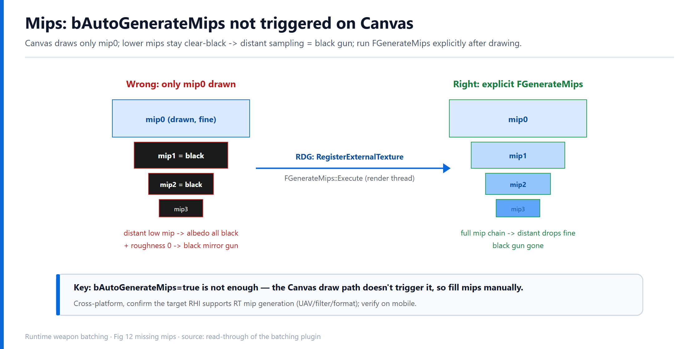
The second trap is equally hidden. The RT was created with bAutoGenerateMips = true, which intuitively should generate mips. But — **bAutoGenerateMips is not triggered on the Canvas draw path.** Canvas only drew mip0; the lower mips stay at the clear color (black) from init.
Consequence: it looks fine up close (sampling mip0), but goes black at distance. A distant weapon samples a low mip, reads an all-black albedo + roughness 0, and becomes a black mirror gun.
The fix is to run mip generation explicitly after drawing mip0, registering the RT into the RDG (Render Dependency Graph) and calling FGenerateMips::Execute:
ENQUEUE_RENDER_COMMAND(WeaponAtlasGenerateMips)(
    [RenderTargetResource](FRHICommandListImmediate& RHICmdList)
{
    FRHITexture* AtlasTexture = RenderTargetResource->GetRenderTargetTexture();
    if (!AtlasTexture || AtlasTexture->GetNumMips() <= 1) return;
    FRDGBuilder GraphBuilder(RHICmdList);
    FRDGTextureRef Ref = RegisterExternalTexture(GraphBuilder, AtlasTexture, TEXT("WeaponAtlasRT"));
    FGenerateMips::Execute(GraphBuilder, GMaxRHIFeatureLevel, Ref, FGenerateMipsParams{});
    GraphBuilder.Execute();
});
This runs on the render thread and fills out the full mip chain. Afterward, distant sampling drops mips normally and the black gun is gone.
To ship cross-platform there’s one more thing to confirm: FGenerateMips depends on the target RHI’s support for RenderTarget mip generation (UAV write, filter sampling, and the specific RT format’s availability). Fine on PC generally; verify it on mobile against the target hardware’s RHI — don’t assume it runs everywhere.
7.5 An incidental acceptance tool
The draw path keeps a switch (WeaponMerge.DumpAtlasRT) that, once on, exports each drawn atlas RT to a PNG on disk. For a system like batching where things are “drawn on the GPU, with invisible intermediates,” having a switch that dumps the atlas to eyeball the layout — no overlaps, whitewash, or black blocks — changes acceptance efficiency entirely. This kind of “observability switch” is worth reserving in any offscreen-rendering system.
8. Texture streaming and “bake first, refine later”
The draw section assumed one premise: the source textures are in VRAM right now and clear mips can be sampled. In reality they may not be — the engine’s texture streaming loads texture mips dynamically by distance/importance, and a just-picked-up weapon’s high-res textures may not have streamed in yet. This raises a timing-design problem.
8.1 The dilemma: wait for quality vs. keep the timing
The intuitive approach is “wait until the textures have streamed in, then build the atlas.” But that blocks the whole build pipeline: the atlas isn’t done, so the mesh can’t build (Build stalls on the atlas step). And a merge request has a time budget — the subsystem has a timeout for one build (a few seconds); on timeout it declares the request failed and the weapon reverts to loose parts. If one weapon’s texture streaming is slow, the whole batch is wasted.
Hence a hard principle: texture quality (refinement) must never block the mesh-merge build timing. Timing is first; quality can be backfilled.
8.2 Bake first, refine later
So it’s designed in two stages:
- Bake immediately (non-blocking): at build time, immediately draw one atlas version from the source textures’ currently resident mips, regardless of whether they’re full. Even with only a low-res mip, draw it out so the build pipeline continues and the mesh merges on time.
- Refine later (async): if some source textures haven’t streamed enough, attach a ticker that checks every 0.25s, and once all sources have streamed enough, redraw the atlas.
// bake immediately from currently resident mips; also request streaming
for (each source texture) SourceTexture->SetForceMipLevelsToBeResident(30.0f);
DrawAtlasGroup(World, AtlasRT, SourceTextures, Transforms, TargetSize);  // bake
if (!bAllSourcesReady)
    ScheduleRefine(World, RefineGroups, Transforms, SlotSizes, TargetSize); // refine
The redraw only changes RT pixels, not the mesh or material — the weapon shows “slightly blurry at first, then sharp,” exactly like normal UE texture streaming, imperceptible to players. The ticker has a 60s give-up threshold so a texture that never streams in doesn’t leak the ticker.
Worth calling out on its own: this is a general async quality-layering strategy — any runtime pipeline that depends on async resource readiness is worth splitting “usable result” from “best result”: produce a usable version from what’s on hand without blocking the main flow, then async-swap to the best version once resources are ready. The weapon atlas is just one instance of it.

8.3 The readiness criterion: don’t use IsFullyStreamedIn
“Have the source textures streamed enough” has a trap. The intuitive check is the engine’s IsFullyStreamedIn(), but for textures with optional mips it always returns false — those top mips are marked optional and may never load, so IsFullyStreamedIn is never satisfied and the ticker waits forever.
The right criterion isn’t “full,” but “enough to draw into this slot“: the texture only occupies a slot of a certain size in the atlas, so sampling into it only uses that resolution — no need to wait for mip0. The criterion is “the current resident mip’s top size ≥ the atlas slot size”:
static bool IsSourceReady(UTexture2D* Src, uint32 SlotSizeX)
{
    if (!Src) return true;
    const int32 NumMips = Src->GetNumMips();
    const int32 ResidentMips = Src->GetNumResidentMips();
    // edge length of the highest-res resident mip
    const int32 ResidentTopSizeX = ResidentMips > 0
        ? FMath::Max<int32>(Src->GetSizeX() >> (NumMips - ResidentMips), 1) : 0;
    // edge length actually needed in the atlas (not exceeding the texture itself)
    const int32 WantedSizeX = FMath::Min<uint32>(SlotSizeX, Src->GetSizeX());
    return ResidentTopSizeX >= WantedSizeX;
}
This ties “ready” to “actual need”: it neither waits forever because of optional mips, nor keeps waiting for full when it’s already clear enough — the most refined bit of this streaming adaptation.
9. Material bind and finalizing the state machine
The atlas is drawn, the UVs are baked; the last step wires them together and closes the state machine cleanly.
9.1 Create the base MID and bind the atlas
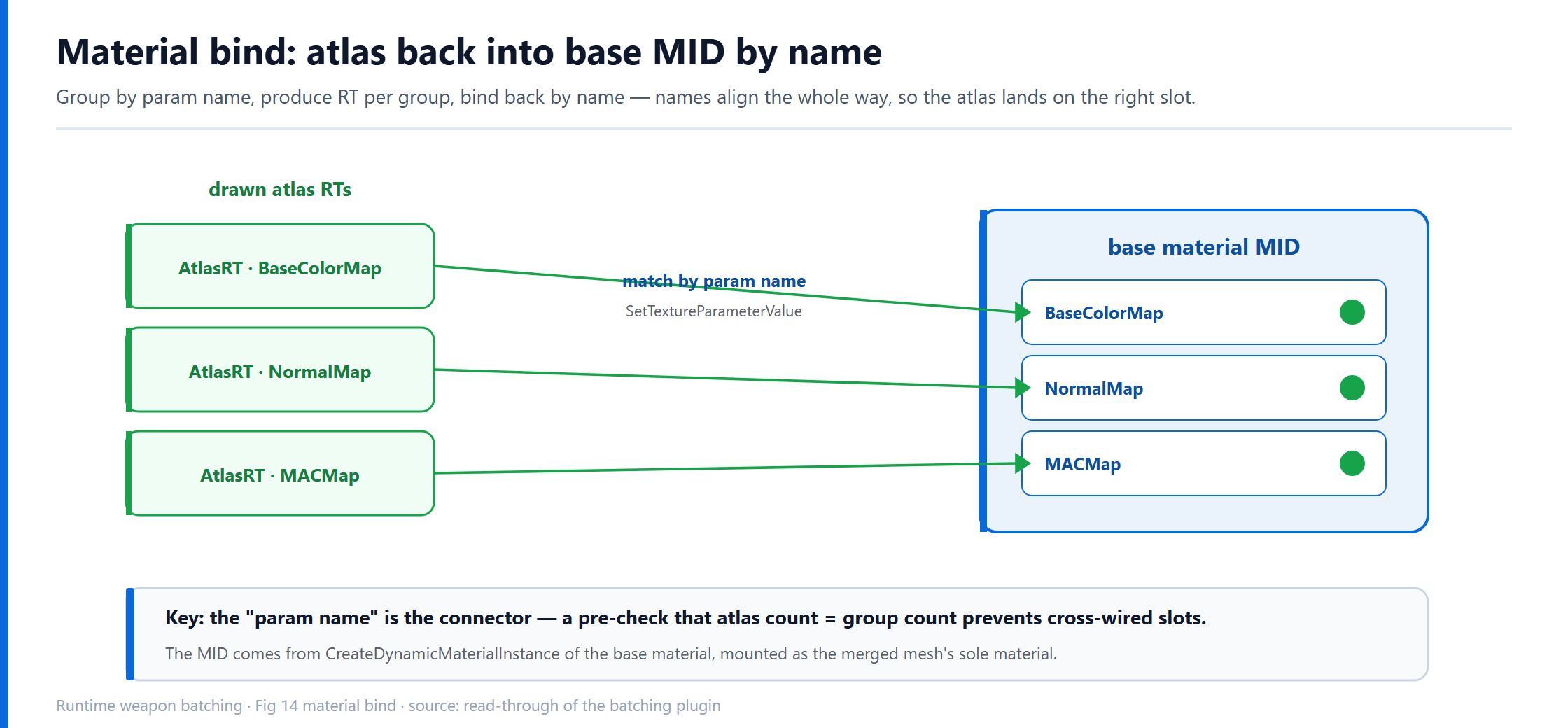
At the end of the draw step, a dynamic material instance (MID) is created from the base material and mounted on the merged mesh as its sole material:
Setup->MergedMID =
    UKismetMaterialLibrary::CreateDynamicMaterialInstance(World, BaseMaterial);
Setup->MergedSkeletalMesh->MergedMaterial = Setup->MergedMID;
Then after the mesh is built, each drawn atlas is bound back into this MID by param name (BindAtlasTextures):
for (each category group i)
    MID->SetTextureParameterValue(
        CategoryGroup[i].MaterialParameterInfo.Name,   // "BaseColorMap" / "NormalMap" / ...
        AtlasRTs[i]);                                  // the matching atlas RT
The param name is the “connector” here: analysis groups by name, drawing produces RTs by group, binding puts them back by name — the names align the whole way, so the atlas lands on the base material’s matching texture slot. Binding has a pre-check (atlas count must equal group count) to prevent cross-wiring.
9.2 Finalizing: call InitResources once, don’t poll
Finally, kick off the merged mesh’s GPU resource init and end the state machine. There’s a timing detail that’s easy to get wrong:
void ActiveStopBuildStateIfBuildSuccess(FMergeJob* Setup)
{
    Setup->MergedSkeletalMesh->InitResources();  // kick off once, that's enough
    // ...notify the upper layer that merge is done...
    Setup->SetState(NULL);                        // end the state machine
}
The key is InitResources() is called once and done, not polled for “is init finished.” Because RHI resource init is done asynchronously on the render thread, polling an “init done” flag on the game thread spins — and spinning drags into the build timeout. The right posture: once the game thread confirms the async-build data is ready, call InitResources once to kick off GPU init, then leave the rest to the render thread, and the render proxy becomes ready automatically once the render thread finishes. This matches the engine’s standard mesh-merge finalize flow — kick off, then let go — don’t wait on the game thread for an event that belongs to the render thread.
10. The two layers end to end, once more
Compressing the previous nine sections into one end-to-end path, a weapon from request to on screen:
- The upper layer assembles a modular weapon and submits an async request to the batching subsystem, carrying the part list, override materials, and
bWantMergeTexture. - The subsystem checks the hash cache: a hit reuses directly; a miss enters the priority queue and is released by the per-frame cap.
- The build state machine starts: Init → load part meshes → (load override materials) → Build.
- Build reads
WeaponMerge.AtlasMode: mesh-only builds directly; atlas runsAnalyzeMergeabilityfirst. - Analysis yields three states: invalid → fail; homogeneous →
Atlas; partly homogeneous →MeshOnly(safety, mesh-only). - If the atlas is possible: packing computes the layout → bake UVs + section mapping → draw atlas RTs (linear end-to-end + explicit mips, bake-first-refine-later if sources haven’t streamed in).
- Build the merged mesh (skeleton / socket / bone map / render-data merge).
- Create the base MID, bind the atlas back by param name.
InitResourceskicks off GPU init, notify the upper layer, end the state machine.
Result: a weapon of a dozen parts, a dozen components, a dozen material slots, converges to 1 merged component + 1 base material (each outlier section adds one) + a set of atlas RTs.
11. Wins, costs, and configuration strategy
Technique done; time to do the math — batching isn’t “on is better,” it’s a set of choices weighed per platform.
11.1 Real wins and costs
Closing the loop on the costs from the intro, a weapon before/after batching:
| Metric | Change | Note |
|---|---|---|
| Component count | N → 1 | a dozen SkeletalMeshComponents converge to 1 merged component |
| Skeletal update / submit / cull | many → single | per-component cost drops linearly with component count |
| Draw call | about -15% | a typical scene goes from ~394 to ~337; more weapons / more people on screen, more win |
| VRAM | up | the atlas is an uncompressed RT, see below |
VRAM separately: one 2048 RGBA8 with full mips is ~21.8MB, and one weapon’s five atlases (BaseColor / Normal / Roughness / Metallic / AO) ~109MB; down to 1024 it’s ~27MB.
And batching itself isn’t free: a merge has build cost (analysis, packing, drawing, GPU resource init) and resident memory (merged mesh + atlas RTs). So it’s only worth it for objects that are frequent, long-lived, or reused in bulk at distance — a main weapon a player holds for ten minutes is worth merging; a loot gun that vanishes in two seconds on the ground isn’t. “Whether to merge” is itself a judgment the system makes.
This is the ledger mentioned repeatedly at selection time: RT + Canvas trades VRAM for implementation cost and maintainability. Components and draw calls both drop, VRAM rises one-way — hence the per-need tiering strategy below.
11.2 Size tiers by view
Not every weapon deserves a 2048 atlas. By “how close, how important” it splits into three tiers:
| Tier | Size | Who | Reason |
|---|---|---|---|
| FPP | 2048 | your own first-person weapon | in your face, sharpest |
| TPP | 1024 | local player’s third-person weapon | mid-range |
| 3P | 1024 | other players’ weapons | farthest, most numerous, most to save |
Distant and other players’ weapons use small atlases, spending VRAM where the player can see it most.
11.3 Whether first-person joins the atlas: a near-view quality trade-off
There’s another split switch (DisableFPPAtlas) controlling “does the first-person weapon join the atlas.” By default first-person doesn’t join — a first-person weapon is in your face, the visual subject you stare at the whole time, and any precision loss from the atlas (size adjustment, 8-bit quantization) gets magnified; and there’s only one first-person weapon, so the draw call it saves is meaningless. Near-view for quality, far-view for performance is the logic of this split. (Here the upper layer passes bWantMergeTexture false, and the analyzer drops to mesh-only right at that gate in Section 4.)
11.4 Uncompressed vs. runtime compression: a real product trade-off
The last, bigger trade-off: why is this atlas on when shipping on mobile, but optional on PC?
Because mobile VRAM is a hard constraint. To turn the atlas on for mobile you must stack runtime texture compression (RTC) to compress the uncompressed RT into ASTC or similar, or the 109MB/weapon VRAM curve simply can’t hold — RTC is the hard gate to enabling the atlas on mobile. On PC, VRAM is relatively roomy and the uncompressed RT’s cost fits; whether to trade the atlas for that 15% draw call depends on how tight the target hardware’s draw-call bottleneck is — a high-end PC where draw calls aren’t the bottleneck may not find it worth 100MB+/weapon to save them.
Batching isn’t “more is better,” it’s finding the balance point along the target platform’s draw-call / VRAM curve. The same technique is “must-on and must-stack-compression” on mobile and “optional, depends on the bottleneck” on PC — that’s what an engineering decision really looks like.

Closing: three transferable design principles
Setting aside the specific APIs, what’s truly reusable in this runtime weapon batching is three design principles:
- Layer it, and make each layer fall back. Mesh merge and the atlas are two layers, decoupled by the three-state analysis; the atlas failing degrades gracefully to mesh-only, so the floor win isn’t lost. Don’t couple a strong condition (material homogeneity) to a weak one (mesh mergeability).
- Quality refinement must never block the critical timing. The build has a time budget, so produce a result immediately from what’s on hand and backfill quality asynchronously (bake first, refine later). Separate “correct but slow” from “good enough and fast,” and let the fast one run through first.
- Offscreen rendering must preserve color space and mip integrity. The RT atlas is linear end-to-end (matching read/write sRGB protocols), and the Canvas path’s mips must be filled explicitly. These two are where “assembling a render pipeline out of upper-layer APIs” silently goes wrong, and only surfaces at specific views/distances.
None of this is unique to weapons or to one engine version — any system that “merges a pile of resources into fewer draw calls at runtime” (character-equipment batching, UI atlases, foliage merging…) hits the same set of problems.
AI collaboration retrospective
- What AI did: read through the whole batching plugin and state machine source, threaded the flow scattered across multiple files into one end-to-end main line, explained each technical point (three-state analysis, two-stage packing, UV baking, the gamma chain, bake-first-refine-later, explicit mips) down to implementation level against the code, and organized it into this structured technical article.
- Where humans stepped in: real-device win numbers (draw call, VRAM), the near-view quality trade-off, the mobile RTC hard gate — these product-level trade-offs can’t be read out of source and are decided by engineering measurement and platform experience; the framing of the article (flow / choice / detail, not migration pitfalls) was human-directed too.
- How we collaborated: AI is especially good at cross-file information integration (threading call chains scattered across files into one line); but the moment performance wins and platform constraints are involved, it still takes real-device measurement to verify — you can’t conclude from reading code alone.