
In a third-person shooter, camera rotation, weapon aiming, and projectile launch do not always align at the same instant. During a fast turn, the weapon target may still be following the view. After the trigger is released, recoil can continue to recover. The update rules and parameters together determine how each weapon handles.
The original prototype development plan established the scope of this work. This article develops its TPS aiming and shooting systems, explaining the original camera, reticle, and firing calculations and their UE integration. The current results are validated in a standalone Lyra prototype and still await integration into the project; they do not establish completion of the extraction-shooter gameplay loop.
Contents
- 1. Camera, Weapon Target, and Firing Direction
- 2. Camera Profiles and Placement
- 3. Aiming Duration and Camera Transitions Keep Separate Time State
- 4. Handling, Target Following, and Persistent Perturbation
- 5. Recoil: Shot Events and Two Spring Groups
- 6. Spread: Angular Width, Random Distribution, and Projectile Direction
- 7. Target Projection and Reticle Layout
- 8. Firing Modes, Charging, and Projectile Motion
- 9. Specialized Paths for Arc, Laser, Seeking, and Spray
- 10. Lyra Integration and State Lifetimes
- 11. Validation Scope and Next Steps

The fixed center provides a viewing reference. The follow circle shows the projection of the current weapon target; firing then applies spread around the aiming basis. The diagram separates the camera from the muzzle to show their different spatial origins. Positions and angles are schematic. Later sections identify the reference points used by each firing path.
The earlier articles, TPS Camera Reconstruction, Part 1: Quantifying Camera Placement and Composition and TPS Camera Reconstruction, Part 2: Validating the Experience, focused on observation and measurement: describing camera placement, comparing composition, and inspecting firing feedback. This article implements independent computation modules based on HD2’s original mechanics and integrates them into a UE5.7 Lyra prototype. The linked earlier articles are in Chinese.
We begin with camera configuration, then examine aiming progress, target following, recoil, spread, the reticle, and firing paths. Parameter tables and worked examples show the inputs and outputs at each step. Formulas use readable mathematical notation; bitwise floating-point comparisons still depend on the operation order and rounding points in the implementation.
The prototype contains 96 player-weapon parameter mappings and 93 camera profiles. Default recoil parameters cover 95 mappings; default angular spread covers 85. The standard reticle supports 79 mappings, while the remaining 17 use explicit fallback displays. These counts describe different modules. They do not mean that 96 original weapon models have been reproduced, or that every weapon has a unique camera or reticle.
Charging, entity projectiles, seeking, and spray each use their own firing paths. Their numerical kernels and UE integration are at different stages, which we distinguish below. This article covers player weapons and TPS firing, rather than complete character locomotion, animation, damage, turret, or drone functionality.
Sections 2–7 explain camera placement, aiming, recoil, spread, and reticle behavior. Sections 8–9 cover ordinary firing and specialized weapon paths. Sections 10–11 discuss UE interfaces and validation scope. Figures labeled as teaching examples use constructed inputs; screenshots and videos come from the existing Lyra prototype. They explain computational relationships and visible results respectively.

1. Camera, Weapon Target, and Firing Direction
The reticle involves three kinds of spatial information.
The first is camera position, orientation, and field of view, which determine how the world is observed. The second is the weapon’s aiming target, affected by handling, periodic perturbation, and recoil state. The third is the direction used for a particular shot, obtained by applying spread to the aiming basis before entering a ray, projectile, or other firing path.
Using one Controller rotation for all three prevents independent observation, following, and firing behavior. During a fast turn to the right, for example, the camera may already face the new direction while the weapon target lags. Camera feedback and target feedback can also differ after firing. Spread acts on individual projectile directions; substituting random camera shake would move the entire image with each sample.
The implementation separates inputs, persistent state, and outputs as follows.
| Layer | Main inputs | Persistent state | Output and consumer |
|---|---|---|---|
| Camera selection | Weapon mapping, stance, action eligibility, overrides | Current selection and transition records | Target profile for camera-frame computation |
| Camera geometry | Profile, pitch, character root and nodes, scene queries | Root position, local offset, FOV history | Camera position, rotation, FOV |
| Aiming state | Aiming eligibility, input, duration parameters | Ready state, aiming progress | Inputs for state selection and aim following |
| Target following and perturbation | Target point, Handling, weapon coefficients, time step | Follow direction, phase, noise, random state | Current weapon target and shared snapshot |
| Recoil | Submitted shot events, two parameter groups, caller scaling | Spring position, velocity, stiffness, pending events | View-related and target-related feedback |
| Spread | Angular widths, mode, firing basis, random state | Random state | Direction for this projectile |
| HUD | Profile, target projection, scaling inputs | Smoothed multiplier and display history | Ticks, center marker, follow marker |
| Firing execution | Mode, interval, charge and projectile configuration | Timers, counters, projectiles or spray particles | Motion, contact, and subsequent presentation |
AimStat determines base aiming duration; Handling controls target following; spread widths define direction sampling; recoil coefficients affect persistent feedback. Recording each parameter and its output helps locate the source of a weapon difference.
UE supplies character, weapon, and scene inputs. One Lyra proxy model carries multiple parameter mappings, allowing numerical differences to be compared with the same visual asset. Resource names retain their configuration identifiers. Commercial names and translations are used only when confirmed.
Configuration, Runtime State, and Scene Inputs
For an ordinary assault rifle, 640 RPM, default angular widths, and the two recoil coefficient groups are configuration. The last successful-shot deadline, spring displacement, and random state are runtime state. Character position, muzzle node, and scene hit point are external inputs to the current computation. Their lifetimes differ.
Configuration is usually selected with the weapon and read repeatedly. Runtime state persists across frames; querying parameters must not reinitialize it. Scene inputs change with the character, camera, and target and must be sampled at the designated stage. Reusing one recoil configuration for ten shots does not restart the spring at rest for each shot. Firing ten projectiles from one initial random state likewise does not reuse the first sample ten times.
Default configuration and runtime modifiers also need separate records. Defaults describe computation without additional modifiers. To confirm whether stance, injury, skills, or other modifiers apply, check the code that reads those values. A more stable image after crouching does not establish that recoil scaling caused all of the change: camera reference points, target perturbation inputs, and HUD display may change simultaneously.
Each frame reads configuration and external inputs, advances existing state, and publishes results. Debug parameters remain separate from original configuration, making configuration differences, input differences, and algorithm differences distinguishable.
Dependencies During Turning, Aiming, and Firing
Consider an assault rifle: the player turns right, holds aim, and fires continuously. The table follows the interaction’s data dependencies. UE input, Ability, camera, and rendering still run through their respective callbacks.
| Time and operation | State change | What this does not yet establish |
|---|---|---|
| Turn the view | Observation direction changes; scene query produces a new desired target | The weapon target has caught up |
| Press aim | Input enters eligibility checks; saved Ready state may change | Camera transition, target following, and progress have all finished |
| Camera update | Select configuration, advance transitions, compute geometry and collision; publish target snapshot | Every firing callback necessarily occurs afterward |
| Press trigger | Firing path checks mode, timing, reload, and other eligibility | A successful shot has occurred |
| Ordinary firing | Read available target, sample each projectile direction, construct and attempt to submit Lyra Target Data | All ordinary hits use entity-projectile motion |
| Successful submission | Save shot mapping and time; notify feedback queue | Recoil has already been fully integrated and displayed in this callback |
| Subsequent camera update | Consume submitted events, advance springs, compute view and target feedback | This feedback necessarily affects the projectile just fired |
| Release and recover | Stop the relevant firing request; continue spring and other persistent updates | All historical state should immediately become zero |
In the current UE integration, successful shots enter a queue before the camera path consumes them and updates recoil. Their feedback may therefore not affect the projectile just fired. An input callback can also precede the camera update and read the previous frame’s still-valid target snapshot. Both timing relationships matter when checking firing results.
Interaction records should associate input, weapon mapping, target snapshot, successful submission, and feedback update. Reticle motion shows the result; event records identify the shot responsible.
2. Camera Profiles and Placement
Profile Parameters and Units
A camera profile stores distances at high, middle, and low pitch; local height; shoulder offset; pitch limits; FOV multipliers; and smoothing rates for offset components. It also contains a reference node and node offset. A height field is therefore not automatically the camera’s height above ground, and a distance field is not the final capsule-to-camera distance.
The following profiles are commonly used by the current base mappings. Distances and offsets are listed in the original coordinate-length units and converted from meters to centimeters in UE. Values are rounded for readability.
| State | Profile | High / middle / low distance | Local height | Shoulder offset | Reference-node offset | Pitch range |
|---|---|---|---|---|---|---|
| Standing Ready | 2 | 1.75 / 1.75 / 1.75 | 0.35 | 0.40 | (0, 0, 1.40) | −75° to 75° |
| Crouched Ready | 3 | 0.30 / 1.00 / 1.00 | 0.40 | 0.47 | (0, 0, 0.75) | −75° to 75° |
| Prone Ready | 4 | 0.10 / 1.50 / 1.00 | 0.50 | 0.65 | (0, 0.20, 0.15) | −45° to 30° |
| Standing non-Ready | 43 | 3.50 / 4.50 / 3.50 | 0 | 0.60 | (0, 0, 1.80) | −70° to 70° |
| Crouched non-Ready | 44 | 1.75 / 2.75 / 1.75 | 0 | 0.60 | (0, 0, 1.30) | −50° to 70° |
| Prone non-Ready | 49 | 0.20 / 4.00 / 4.00 | 0.40 | 0.60 | (0, 0.50, 0.25) | −30° to 30° |
The assault rifle, pump shotgun, heavy machine gun, and rail weapon can reference the same profiles in these base stance mappings. Shared placement still allows different aiming durations, following, recoil, and spread parameters.
Prone profiles alone do not establish that prone movement, animation, and input have been fully ported. The camera can preview prone parameters before the character action chain is validated separately.

Selection Eligibility and Override Priority
Camera selection involves more than choosing profile 2 on aim press and 43 on release. It first handles blocked writes or failed eligibility, then global modes, special states, and overrides, before reaching the base weapon-holding and stance mapping. Overrides also have different priorities.
The base mapping table describes selection under normal conditions. The complete selector also handles action and special-state restrictions. Writing a Ready profile directly can move the camera into an aiming position before the associated internal conditions are satisfied.
The port preserves selection order and passes UE character state as input. Action-state producers that are not fully connected remain explicitly scoped. Unidentified original flags cannot be named sprint, roll, or another action solely from one observed frame.
Pitch Affects Both Distance and Field of View
Normalize current pitch within pitchLow and pitchHigh:
t = clamp((pitch − pitchLow) / (pitchHigh − pitchLow), 0, 1)
Each half then uses a square-root curve:
t ≤ 0.5: k = sqrt(2t), interpolate from low to middle
t > 0.5: k = sqrt(2(t − 0.5)), interpolate from middle to high
Distance and the FOV multiplier use the endpoints for the corresponding half. At t=0.25, for example, k≈0.7071, rather than the linear weight 0.5. Normalized pitch and distance interpolation do not use the same proportion.
The FOV multiplier is combined with external view input. Distance is then scaled using the resulting FOV:
FOVdegrees = fovMultiplier × inputAngleDegrees
distanceScale = (1 − z) + z × 48 / FOVdegrees
distance = distanceScale × distanceInterpolatedWithinThisHalf
z blends the distance/FOV relationship. At z=0, this FOV ratio does not affect distance; at z=1, the full 48/FOVdegrees ratio applies.
The base adapter currently uses an external view input of 60°. With profile 2, multiplier 1, and z=1, this geometry stage gives 1.75×48/60=1.40 m. The table’s 1.75 is therefore not the final camera distance. This example excludes node transforms, state blending, and collision correction.

From Local Offset to World Space
The local camera target is constructed as:
localTarget = (shoulderSign × side, −distance, height)
Character-root, reference-node, and local-offset histories are processed separately before conversion to world space. Ordinary component smoothing uses a clamped update:
alpha = clamp(rate × dt, 0, 1)
next = old + alpha × (target − old)
Profile 2 has local rates (10,10,5). At dt=1/60 s, the first two axes cover about one sixth of the remaining difference per step, and the third about one twelfth. A rate of 10 is neither a ten-second duration nor a fixed 0.1-second animation. Continuous convergence has no universal completion time, and clamping changes behavior at large time steps.
Root-position handling has additional branches, so the complete geometry cannot be reduced to three ordinary interpolations. Collision correction runs after candidate placement and uses the collision anchor and scene query to adjust the camera. UE supplies the scene-query service; query shapes, collision filtering, and scene assets still require validation separately from numerical geometry.
Coordinate conversion is also part of the interface. The current adapter maps original (X,Y,Z) to UE (Y,X,Z)×100. Converting units without swapping axes would apply shoulder offset in the forward/backward direction. Capsule center also differs from a foot-root anchor. A foot anchor must subtract capsule half-height, or the added reference-node height will raise the entire result.
Camera Parameters and Observation Conditions

Shoulder offset determines which side of the reference frame the camera occupies. Rearward distance and local height also affect composition. The top view shows the two horizontal components, while the earlier stance diagram explains reference nodes and height: different components of the local placement calculation.
When changing shoulder offset, inspect horizontal character occupancy, nearby occlusion, and the muzzle-to-target angle. It does not directly determine projectile spread. When changing local height, hold the reference node, root position, and other offsets constant. Changing node height and local height together can produce similar images without confirming either parameter’s interpretation.
Similar character screen height does not imply identical distance and FOV. A more distant camera with a smaller FOV can produce similar occupancy while changing background perspective, near/far size relationships, and side occlusion. Image measurement compares composition; parameter computation explains it. Both are needed.
The current left-shoulder calculation changes the lateral sign. It does not automatically mirror weapon animation or move the model’s muzzle. After a left-shoulder switch, a right-handed muzzle can remain on the right. Close-range firing must still check the actual origin and target direction; camera switching alone does not mirror the complete weapon geometry.
Collision correction must also remain separate from configured target distance. An obstacle can move the final camera closer without permanently shortening the profile. Once the obstacle clears, recovery continues from saved state. Writing the collision-adjusted distance back into configuration could make the next entry start at an incorrect distance.
Camera validation covers fixed-pitch placement, pitch changes, contraction near a wall, and recovery after moving away. A single open-space frame checks static placement, but not smoothing history or collision fallback.
3. Aiming Duration and Camera Transitions Keep Separate Time State
AimStat and Base Aiming Duration
Aiming duration uses AimStat and fast/slow endpoints. The kernel first converts the value to an integer, then normalizes it with floating-point division and applies an upper limit:
t = min(float(int32(AimStat)) / 100.0, 1.0)
duration = (1 − t) × slow + t × fast
The calculation has no lower clamp. The examples use valid default configurations without introducing negative-parameter tests, and the port retains the original upper limit.
For these mappings, fast≈0.09 s and slow=0.50 s:
| Configuration identifier | AimStat | Base duration | Interpretation |
|---|---|---|---|
| assault_rifle | 65 | 0.2335 s | Interpolate between slow and fast with weight 0.65 |
| pump_shotgun | 65 | 0.2335 s | Same duration, without implying other mechanics match |
| heavy_mg | 0 | 0.5000 s | Use the slow endpoint |
| railgun | 35 | 0.3565 s | Interpolate with weight 0.35 |
This duration controls aiming progress, not camera-position interpolation or firing interval. Assigning 0.2335 seconds to every smoothing module would change their state relationships.
Previous-Frame Ready and Current Input
Aiming progress advances using the saved Ready state from the previous frame:
step = dt / duration
Previous frame Ready: progress = clamp(progress + step, 0, 1)
Previous frame non-Ready: progress = clamp(progress − step, 0, 1)
Only afterward do current input and eligibility determine the new state. A button press can change Ready for the next step while progress is still retreating. Overwriting Ready before advancing progress changes when input takes effect.
A true input value is not sufficient for Ready eligibility. Weapon description, configuration eligibility, action inputs, and held state all contribute. The adapter translates UE input into these conditions rather than allowing one right-mouse boolean to bypass them.
Unfinished Camera Transition Records Persist
Camera transitions have their own record queue. On a selection change, rules are looked up using old type, old profile, new type, and new profile, with both exact and wildcard matches. Records retain delay, progress, direction, and curve type and advance with camera frames.
Releasing aim partway through entry can therefore follow a different history from releasing after arrival. Restarting a fixed curve from zero on every input change would lose reversal state.
Transitions support steps, linear curves, several Bezier forms, and other curves. One quintic example is:
w(t) = 6t⁵ − 15t⁴ + 10t³
Its weight is about 0.1035 at t=0.25 and 0.8965 at t=0.75, giving gentler endpoints than linear interpolation. Not every profile transition uses this curve, and transition types do not all share identical clamping behavior.
Ready progress describes the aiming state’s advancement; camera transition records describe movement from the old camera state to the new one. One input can affect both, but each keeps its own history and update rules.
Mid-Transition Release and History
Using the assault rifle’s 0.2335-second duration as a teaching input gives a progress increment of about 0.07138 at 60 Hz. If Ready was already true and seven steps advance, progress reaches about 0.4996. Releasing then requests exit, but that frame’s progress still reads previous-frame Ready. Later updates reduce progress through the non-Ready branch.
Seven steps are simply the length of this worked example. progress≈0.5 can describe entry into aim or a newly received exit request. Camera placement also depends on transition records. Current progress and button state alone lose that history.
Camera transitions must handle their own reversal. A reverse request while approaching Ready should not first jump back to the start and replay an exit curve. Records retain progress, direction, delay, and source. Replacing them with a new 0.2-second animation on each press may look correct at stable endpoints but introduce position or velocity discontinuities during repeated input.
Input tests should cover taps, holds, stance changes, and action restrictions. Stable endpoint screenshots check endpoint configuration; transition history and reversals require continuous-input tests.

4. Handling, Target Following, and Persistent Perturbation
Target Following Updates a Direction Frame

The image shows separation between circle and center; the computation retains direction and its history. The right diagram labels the old direction, desired direction, and interpolated result for the formulas below. Projection also depends on camera, target distance, and perturbation, so pixel separation cannot directly become a directional error.
When the player turns, the desired target changes immediately. The current weapon target follows at a rate derived from Handling:
t = clamp(Handling / 100, 0, 1)
A = 1 + 19t²
B = 1 + 0.5t
rate = 3.1400001 × A × (Ready ? B : 1)
alpha = dt × rate
Handling enters a squared term, so doubling it does not double the rate. Ready applies coefficient B; whether alignment completes in this step still depends on the final interpolation weight.
| Configuration identifier | Handling | Non-Ready rate, approx. | Ready rate, approx. |
|---|---|---|---|
| assault_rifle | 59 | 23.91 | 30.96 |
| assault_rifle_ap | 47 | 16.32 | 20.15 |
| pump_shotgun | 65 | 28.35 | 37.56 |
| heavy_mg | 0 | 3.14 | 3.14 |
| railgun | 35 | 10.45 | 12.28 |
For the assault rifle in Ready at 60 Hz, alpha≈0.516. This is a directional interpolation weight, not 0.516 meters of target movement per frame.
The implementation constructs direction frames from a reference origin and the old/new targets, then performs shortest-path quaternion interpolation. Very close directions use a normalized linear form; alpha≥1 selects the new target directly. Target distance is handled separately when constructing output. A world-space Lerp(oldPoint,newPoint,alpha) is therefore a different algorithm.
The distinction matters during fast sweeps or at short range. Position interpolation follows the chord between targets; direction interpolation changes orientation around the observation origin.
Periodic Perturbation and Random Noise Keep Their Own State
Target perturbation stores amplitude, frequency, phase, and two noise states rather than using a single sine wave. Caller input, wielder parameters, and weapon coefficients jointly construct the amplitude target, which is smoothed. Frequency uses independent coefficients.
Each noise axis performs a random walk followed by filtering. Omitting the branch that takes the target directly when error is tiny, the main update is:
rawNext = clamp(raw + (2u − 1) × 10 × dt, −1, 1)
filteredNext = filtered + clamp(7 × dt, 0, 1) × (rawNext − filtered)
u is the current random sample. Retained noise state makes offsets in adjacent frames related. Adding independent Random(-1,1) values to screen coordinates each frame produces high-frequency jitter rather than this continuous drift.
Phase advances with frequency and time step. Periodic, noise, and spring terms then form an offset, written here in readable notation:
x = springX + (0.5sin(phaseX) + noiseX) × amplitudeY × K
y = springY + (cos(phaseY + π) + noiseY + 1) × amplitudeY × K
target = candidate + (Right × x + Up × y) × distance
K≈0.005555556 is a fixed kernel scale. Both recovered expressions read the same amplitudeY; that confirmed access must not be changed merely because the variable name suggests separate axes. Frequency also reads caller input and wielder coefficients: 0.5×F×wielder2 horizontally and F×wielder3 vertically. F is not one final oscillation frequency shared by every weapon.
Multiplication by target distance scales the disturbance in world space. The HUD then projects the world target into a visible screen displacement; the parameter is not a fixed pixel count.
UE Fixed-Step Scheduling and Input Sampling
The aiming-feedback adapter advances following, perturbation, and HUD multipliers at 60 Hz, then interpolates for rendering. Catch-up steps use the latest camera sample; they cannot reconstruct unsampled mouse-input history. This is UE scheduling policy, not a complete reproduction of the original scheduler.
Initial wielder amplitude, feedback start time, and the optional experiment mapping UE movement speed into motion inputs also belong to the adapter. Available defaults do not establish that every original dynamic producer is connected.
Before comparing Handling, confirm that following is enabled. Keep parameter tables, switches, and runtime state together. A parameter panel establishes displayed configuration; actual updates require runtime records.
Handling Also Affects Amplitude Smoothing
Target-follow rate and perturbation-amplitude change rate have different consumers. The amplitude update compares the lengths of target amplitude T and current amplitude A to determine how far it can move in this step:
ratio = |T| == 0 ? 0 : min(1, (|T| − |A|) / |T|)
blend = (Handling / 100) × ratio + (1 − ratio)
step = [0.35 × (1 − blend) + 2 × blend] × dt
delta = T − A
If |delta|≤step, the target is reached; otherwise movement along the difference is limited to step. A nonpositive step has a hold-current-value branch. This limits the amplitude vector’s change length, rather than applying one percentage independently to each axis.
ratio has only an upper limit. Adding a lower clamp or replacing all amplitude changes with FInterpTo would alter the recovered behavior. Growth and decay have different length relationships.
With teaching inputs |T|=1,|A|=0,Handling=59, ratio=1, blend=0.59, and at 60 Hz step≈0.02206. This demonstrates gradual amplitude buildup. It is neither 0.02206 pixels per frame nor a guarantee that the complete perturbation settles after a particular number of frames.
The prototype also constructs upstream amplitude and frequency inputs from stance and optional motion input. Standing amplitude endpoints are 1 and 4; crouched endpoints are 0.75 and 3; frequency-input endpoints are 3 and 12. Normalizing UE velocity to 0–1 is optional. Those endpoints come from fixed condition ranges. The original calculation that produces inputs from motion state has not been fully recovered, so the endpoint values and the UE-velocity adapter policy are recorded separately.
Camera Targets and Muzzle Reference Points
Following needs a reference origin, while perturbation can use another. The adapter can query a candidate surface point along the view. Following uses that query origin; perturbation distance can use the character’s muzzle node. The coordinates need not be identical.
A nearby target therefore cannot always be replaced by a fixed distant point. Scaling perturbation over hundreds of meters when the actual target is two meters away can exaggerate the screen/muzzle discrepancy. Using a hit surface point is an explicit UE scene-query policy.
Node bases also determine offset directions. The recovered algorithm requires the corresponding firing-node axes. The prototype commonly uses camera Right and Up and retains a diagnostic path for testing node axes. A correct kernel does not establish equivalence between Lyra’s animated muzzle node and the original node. Record both origin and basis; a fixed screen offset cannot correct this spatial discrepancy.

Video 1: Turning and reticle following with four weapon parameter mappings.
The footage uses rifle, heavy machine gun, bolt_action_rifle, and standard-pistol parameters in sequence, showing slow turns, fast turns, stopping, and firing. All use Lyra proxy models; the labels do not mean four original weapon models have been ported. The first two firing sequences also include magazine depletion and reload, so their entire tails cannot be treated as undisturbed recoil recovery. Follow-rate semantics remain defined by this section’s formulas. The video alone does not establish numerical equivalence.
5. Recoil: Shot Events and Two Spring Groups
Shots Write Velocity; Springs Continue to Evolve
Each recoil slot retains A and B spring groups, including horizontal/vertical displacement, velocity, and stiffness. A shot writes an impulse into velocity, followed by persistent fixed-step integration. Releasing the trigger stops new events while existing springs recover. A single AddPitch cannot express this process.
The core update is:
h = 1/60 s
vNext = v − (35v + k × p) × h
pNext = p + vNext × h
p is angular displacement, v velocity, 35 the damping coefficient, and k current stiffness. Velocity is updated first, and the new velocity advances position. Using old velocity first changes the discrete system.
Frame time is clamped to 0–1 seconds, accumulated, and consumed in fixed steps. A displacement length above about 0.001745329 rad enters the active branch, with target stiffness 150/Scale; nonpositive Scale uses a protected value of 150. The inactive branch targets 75. Stiffness changes per fixed step are limited to about 0.833333 and 1.666667 respectively, rather than jumping to target. Some branches also constrain negative vertical displacement. A standard damped-oscillator curve alone cannot describe all recovery behavior.
The Five Recoil Coefficients
Each shot-parameter group contains C0…C4. The first two feed horizontal/vertical base strength, the third selects horizontal sign, and the last two control randomness on their respective axes. They are velocity-injection coefficients, not five final camera angles.
With caller scale s and random values u0,u1,u2:
X0 = s × C0
Y0 = s × C1
X = X0 × [1 + (1 − C3) + u0 × C3]
Y = Y0 × [1 + (1 − C4) + u1 × C4]
sign = C2 ≥ u2 − 0.5 ? +1 : −1
X = sign × X × π/180
Y = Y × π/180
The angle conversion helps explain why C1=20 does not mean 20° of upward camera rotation per shot. Scaling, random terms, velocity writes, and multiple integration steps still follow.
Some default coefficient groups are:
| Configuration identifier | B group: C0,C1,C2,C3,C4 | A group: C0,C1,C2,C3,C4 |
|---|---|---|
| assault_rifle | 7,10,0,0.1,1 | 5,20,0,0.1,1 |
| pump_shotgun | 40,40,0,0.1,1 | 50,200,0.5,0.1,1 |
| heavy_mg | 50,80,0,0.1,1 | 15,30,0,0.1,1 |
| railgun | 10,25,0,0.1,1 | 3,25,0,0.1,1 |
For the assault rifle’s B group, teaching inputs s=1,u0=u1=u2=0.5 give horizontal injection before angle conversion 7×1.95=13.65, and vertical injection 10×1.5=15. These feed the spring; they are not final visible angles. The chosen random values illustrate the formula and are not claimed samples from a real shot.
The groups have different velocity-write rules. A replaces the corresponding velocity. B replaces it only if the new absolute value is greater. If a new horizontal impulse opposes existing horizontal displacement and that displacement’s absolute value exceeds 0.01, the injection is additionally multiplied by 0.0625. Each shot processes B before A, fixing random consumption order as well.
Selecting Outputs Per Axis Across Slots
Feedback selects the displacement response with greatest absolute magnitude separately for each axis across slots; it does not sum all slots. Horizontal and vertical outputs can consequently come from different slots. One global spring cannot retain the same history during weapon changes or overlapping events.
Caller scaling also requires evidence for its meaning. The code includes injury-flag-dependent scaling, while the prototype has a global gain to supply missing upstream inputs. These cannot all be labeled crouch recoil reduction, nor can an adapter constant represent complete original character-state computation.
UE notifies the recoil queue after successful shot submission, retaining mapping, event sequence, and logical time. Trigger presses, rejected attempts, and actual launches remain distinct, especially for insufficient charge or missing seeking lock. Otherwise the system could generate full recoil without launching anything.
Continuous Fire Changes State, Not Just Shot Count
If the spring is at rest before the first shot, injection begins from zero velocity. By the second shot, displacement, velocity, and stiffness already exist. New input is compared with those states. B may fail to replace the old velocity; A replaces it, and an opposing horizontal input may be reduced. Two shots generally cannot be reproduced by copying and adding two first-shot curves.
After release, injection stops but recovery continues. Displacement, velocity, target stiffness, and branch constraints determine recovery; one return duration is insufficient. Zeroing velocity on release or applying an extra return-to-center curve adds a second recovery system outside the original spring.
Weapons also cannot be ranked by C1 alone. Both coefficient groups, firing cadence, and persistent state contribute. Greater vertical strength does not guarantee greater final screen displacement at every instant.
Default UE Frame Batching and the Experimental Shot Timeline
The kernel supports five slots; successful shots in the current player test range mainly write slot 0. The other slots do not establish that all original equipment associations are connected. The adapter still supplies injury scaling, slot ownership, and some character states.
The default camera-frame path consumes queued shots together, then advances the frame’s spring. If two shots arrive in one frame, their velocity writes occur sequentially before integration; this does not guarantee the exact original interval between them.
An experimental timeline stores event times and reschedules or replays them against fixed steps. It is disabled by default and checks timing differences rather than reproducing the entire original scheduler. Logical firing time, recoil-consumption time, and display time must remain separate.
At both 30 and 120 FPS, 1/60-second substeps can use identical integration lengths while receiving events on different substeps. Comparing frame rates therefore requires injection sequences and random-state records to distinguish numerical integration error from scheduling differences.

6. Spread: Angular Width, Random Distribution, and Projectile Direction
Full Angular Width and Maximum Half-Angle
Spread configuration supplies horizontal/vertical angular widths and a mode. Widths enter direction computation in milliradians and describe the full width along each axis; maximum deviation typically corresponds to half that width. They are neither pixels nor meters at the target.
| Configuration identifier | Full horizontal width | Full vertical width | Default mode |
|---|---|---|---|
| assault_rifle | 2 mrad | 2 mrad | 0 |
| assault_rifle_ap | 1 mrad | 1 mrad | 0 |
| heavy_mg | 5 mrad | 5 mrad | 0 |
| railgun | 0.1 mrad | 0.1 mrad | 0 |
| pump_shotgun | 150 mrad | 120 mrad | 0 |
A spread row for pump_shotgun does not establish that every field of its ordinary firing data is usable. Direction-kernel support and a valid projectile count belong to different modules.
U² Radial Sampling
Mode 0 consumes two random values U,V per sample:
r = U²
φ = 2πV
sampleX = 0.5 + 0.5r cosφ
sampleY = 0.5 + 0.5r sinφ
θx = 0.001 × WidthX × (sampleX − 0.5)
θy = 0.001 × WidthY × (sampleY − 0.5)
Combining the steps gives:
θx = 0.0005 × WidthX × U² cosφ
θy = 0.0005 × WidthY × U² sinφ
The radial transform is U²; uniform-area disk sampling typically uses sqrt(U). These produce different impact densities and are not interchangeable simply because both have circular boundaries.
With U=0.5,V=0, the assault rifle’s horizontal angle is 0.00025 rad. Ignoring ballistics, target changes, and other perturbation, that corresponds to about 2.5 cm at 100 meters. Its maximum horizontal angle is 1 mrad, or about 10 cm under the same approximation. The first value is a sample; the second is the boundary implied by angular width.
Unequal horizontal and vertical widths stretch the distribution along the axes. Nonzero modes have different sampling relationships and cannot all be described as this disk distribution.
Random State and Direction Basis Are Inputs Too
Random generation uses persistent 64-bit state:
seedNext = seed × 0x5851F42D4C957F2D + 0x14057B7EF767814F
u = float(seedNext >> 32) × 2⁻³²
State arithmetic wraps at 64 bits. Mode 0 consumes two updates per sample; additional projectiles consume subsequent state. An initial seed alone cannot reproduce results if projectile count or random-call order changes.
Applying the sampled angles also depends on the supplied basis and a specified order of rotations around different axes. Adding the same angles to a UE Rotator does not guarantee the original axis order.
The current default spread does not add generic aim or running multipliers. Dynamic modifiers require their own confirmed sources and conditions. Adding them before checking default width, sampling distribution, and basis mapping makes error sources harder to distinguish.
Observing Spread Separately from Aim Drift

Record reticle display and projectile directions separately. The circle shows the projected target; outer ticks follow HUD layout rules. A projectile direction is sampled around the corresponding basis only when firing succeeds. The two experiments below separate persistent drift from random spread.
Let the pre-shot weapon direction be D, with spread producing D'. During continuous fire, the next D can already have changed because of following, perturbation, or recoil. Final impact width therefore combines changes in the per-shot basis with random deviations around that basis.
To validate default spread, fix basis direction, distance, mapping, and sample count, then retain each direction before and after spread. Enable dynamic targets and recoil separately when validating the complete firing experience. This distinguishes sampling distribution from persistent feedback.
A single shot with multiple projectiles can share one firing basis while consuming a random sample per projectile. Consecutive shots read new bases at different times. Ten impacts in either case do not imply identical basis-sampling times.
Distribution comparison should check center density, axis proportions, and random consumption as well as maximum range. Mean and maximum radius alone can miss an accidental substitution of uniform-area sampling for U². With the same random sequence, compare angles first, rotated directions second, and scene hits last to locate sampling, coordinate, or collision differences.

Video 2: Ordinary firing and parameter mappings, using the first 18 seconds of the source recording.
This footage shows ordinary firing, ammunition consumption, and target-surface marks. Target perturbation and direction following were disabled in this version’s panel, so it cannot validate the preceding following mechanism. Surface marks alone also cannot establish the complete spread probability distribution. Later special-weapon segments are excluded; they require independent footage of their respective execution backends.
7. Target Projection and Reticle Layout
Three Display Elements Have Different Responsibilities
The HUD handles outer ticks, the screen-center marker, and the target-follow marker separately. Profiles determine tick count, angles, graphic resources, and expansion. The center marker provides a screen reference; the follow marker reads the projected target snapshot.
Standard profiles also contain type and eligibility flags. Some elements depend on Ready, some remain visible, and some are hidden. Specialized configurations unsupported by the ordinary path use a fallback. Each weapon’s elements must therefore follow its profile; their sizes cannot all be interpreted as original spread ranges.
Outer Expansion Uses Maximum Axis Deviation
The HUD first smooths a scaling multiplier:
mNext = m + clamp(30dt, 0, 1) × (mTarget − m)
It then derives extent from projected target deviation:
deviation = max(abs(screenX − centerX), abs(screenY − centerY))
extent = max(base × multiplier, deviation + padding)
t = clamp(extent / normalization, 0, 1)
response = (1 − t) + t × responseEndpoint
The first expression selects the larger horizontal/vertical deviation. At (20,20) relative to center, it gives 20; Euclidean distance would be about 28.28. Here, extent is a layout range computed using maximum axis deviation.
For standard profile 0, base=32,padding=0,normalization=100,responseEndpoint=0.75. With multiplier 1 and maximum deviation 40 in UI coordinate units:
extent = max(32,40) = 40
t = 0.4
response = 0.6 + 0.4×0.75 = 0.9
Profile 9 instead uses base=16,padding=10,normalization=64,responseEndpoint=0.25 and three ticks. These change base size, padding around deviation, and response curve. Resolution and UI transforms convert original UI coordinates to pixels; a table value of 32 is not necessarily 32 pixels in every window.

Check Graphics and State Computation Separately
Ticks read resources by index rather than copying the first texture into an arbitrary number of ticks. Some profiles distinguish layout angle from texture rotation. Three visible ticks do not establish that all three textures should rotate outward.
Outline dimensions also have independent rules. Recovered resource keys and dimensions do not establish recovery of original GPU composition, all eligibility conditions, or specialized HUDs. Slate ordering, world-to-screen projection, and some center-element combinations remain UE adaptations, distinct from standard layout-kernel coverage.
The display retains previous and current samples and interpolates with a delay of roughly one fixed step to reduce render-rate jitter. It must not advance random state, phase, or recoil again; otherwise reticle rendering and firing in the same frame could read different targets.
Target snapshots therefore carry weapon identity, mapping, and freshness checks. A weapon change invalidates the old snapshot rather than passing the old weapon’s target to the new one. This can be difficult to notice with one weapon but cause reticle jumps or old-direction firing during rapid mapping changes.
Coordinates and Elements in the Screenshot
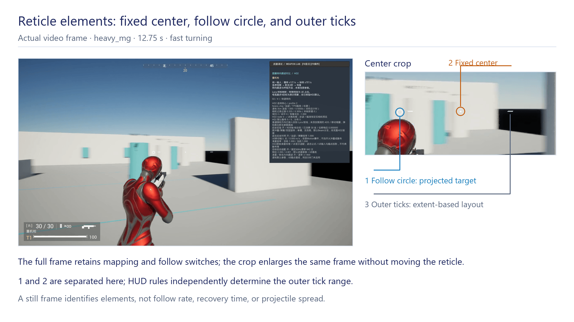
Orange marks the fixed screen center, blue the follow circle, and gray the outer ticks. During this fast-turn sample, the circle has moved left of center while the outer ticks remain arranged around their own layout center. They represent center reference, target projection, and HUD layout range respectively. Circle-to-center distance is not projectile spread.
The full frame and crop identify display elements; they do not provide the target’s complete motion history. Turning and stopping are shown in the synchronized-input comparison in Video 3.
In profile 0’s teaching example, a maximum deviation of 40 produces extent 40. If deviation returns to 10 while the multiplier stays at 1, base 32 controls extent. The outer range remains bounded by the base as deviation decreases. Profile 9 adds padding for the same deviation.
When window size or DPI changes, check the UI-to-pixel transform before changing base configuration. Changing base directly can introduce incorrect scaling at other sizes. Projection y, tick-layout angle, and texture-rotation sign also require separate checks; apparently centered coordinates do not establish correct rotation.
Display interpolation smooths ordinary reticle state but does not repair invalid targets. Identity changes, backward time, or excessive time jumps reset display history under adapter rules, avoiding invalid interpolation between different weapons’ targets.
8. Firing Modes, Charging, and Projectile Motion
Mode, Cadence, and Projectile Count Are Separate Checks
Ordinary firing first distinguishes automatic, semiautomatic, and burst-count conditions. In the current scope, mode 1 permits continued automatic firing, mode 2 requires the current input-cycle count to be zero, and mode 3 requires it to remain below the configured limit. The assault rifle lists [1,2,3] with a burst limit of 3.
Firing interval is checked separately:
interval = 60 / RPM
The assault rifle’s 640 RPM gives 0.09375 seconds; the heavy machine gun’s 600 RPM gives about 0.1 seconds. Holding input does not bypass cadence or other eligibility requirements.
Projectile count is not mode count. Some shotguns launch multiple projectiles and require multiple direction samples; one successful-shot notification must not inject full recoil separately for each projectile. Conversely, a zero projectile-count field must not automatically mean firing zero projectiles or be silently replaced with one.
The ordinary pump_shotgun row retains 80 RPM and a 0.75-second interval, but its zero projectile count is unsupported in that ordinary data path. Its spread and recoil remain separately analyzable; ordinary firing does not yet have a complete valid parameter set.
Lyra still handles input, Ability, reload, and some ammunition flow. Recovered cadence is integrated into test-range firing, not the complete original weapon lifecycle. Semiautomatic deadlines persist in Pawn adapter state and must not be cleared unconditionally by Ability reconstruction or temporary switching.
Input Timing for Semiautomatic, Burst, and Automatic Fire
Semiautomatic input grants one firing opportunity per press. If a press is rejected during cooldown and then held, the prototype does not fire automatically when cooldown ends. Retaining that request would alter the one-press, one-opportunity rule.
Burst mode retains successful submissions during one press. Once the three-shot limit is reached, continued holding cannot start another burst. The current UE policy truncates unfinished bursts on release and requires a new press. This input policy remains separate from the recovered count condition and is not claimed as complete original input behavior.
Automatic fire also faces clock drift. Setting every next time to now+interval accumulates callback lateness. An optional continuous clock instead advances scheduled deadlines:
scheduledTime = nextDeadline
nextDeadline += interval
If the deadline has arrived, attempt this shot
A teaching sequence at 640 RPM is 0,0.09375,0.18750,0.28125…. If a callback arrives at 0.10 seconds, the second scheduled time remains 0.09375 and the third 0.18750, rather than shifting to 0.19375.
Catch-up processing also has a budget. The experimental path processes at most four due events per call and retains later deadlines. On release, it processes only due items strictly before the release edge and creates no later shots. Reload, cancellation, and mapping changes stop processing rather than using the same catch-up rule.
The continuous clock is a single-player experiment disabled by default; the ordinary Lyra Blueprint lifecycle remains. This sequence explains the option, while normal startup behavior must be checked against the path actually enabled.
Three Charge-Time Thresholds
Charged weapons use minimum, ordinary, and upper thresholds. They also distinguish the running timer from the duration latched on release.
| Configuration identifier | Minimum | Ordinary | Upper |
|---|---|---|---|
| plasma_rifle_charge | 0.01 s | 1.00 s | 1.00 s |
| plasma_pistol | 0.01 s | 0.75 s | 3.00 s |
| arc_thrower | 1.00 s | 1.10 s | 1.20 s |
| plasma_blaster | 1.00 s | 2.50 s | 2.60 s |
| railgun | 0.45 s | 0.50 s | 3.00 s |
The ordinary branch limits timer advancement at the ordinary threshold. Certain modes can exceed it, without justifying a universal upper clamp absent from the original code. Release eligibility also checks minimum duration, action eligibility, and cooldown. Passing that check permits further processing; it does not establish successful projectile creation.
Latched duration selects the segment. Below the ordinary threshold:
w = clamp((latched − minimum) / (ordinary − minimum), 0, 1)
factor = (1 − w) × left + w
Above it:
w = clamp((latched − ordinary) / (upper − ordinary), 0, 1)
factor = (1 − w) + w × right
The implementation also handles degenerate denominators when endpoints match. Different outputs read different left/right factor pairs; not every factor is a damage multiplier.
For the rail weapon, minimum is 0.45 seconds and ordinary is 0.50. Latching at 0.475 in the low segment gives w=0.5; factor group 0 has left value 0.7, producing 0.85. Latching at 1.75 in the upper segment gives w=0.5; factor group 1 has right value 2.5, producing 1.75. Group numbers are retained because each consumer cannot yet be assigned a confirmed gameplay meaning. These examples must not be combined into one power curve.
The running timer also supplies a separate recoil scale:
recoilFactor = 1 + clamp(current / ordinary, 0, 1)
Both latched and current duration are useful. One chargePercent would lose state. Segment-based projectile-type mappings must also be read separately; a zero type’s fallback meaning cannot simply be interpreted as no shot.
Charge Release and Duration Latching
On press, UE retains mapping, mode, and start time and initializes a fixed-step count. While held, it checks mapping/mode changes, firing restrictions, and valid charge parameters. Loss of eligibility cancels charging and waits for release to consume the input; switching back does not restore old progress.
Release first advances to the currently computable timer point, then checks eligibility. Below minimum, nothing fires. Qualified releases enter the corresponding path: arc weapons discharge, while other connected configurations can still use the Lyra firing proxy. Timer and charge display are cleared afterward.
Piecewise factors and projectile-type rules have numerical implementations. The Lyra proxy connects charge input to release firing, but factors are not yet fully connected to damage, penetration, or projectile attributes. Progress bars and firing footage mainly check input eligibility and proxy firing.
Overcharge damage, explosions, and self-damage are outside current validation. Here upper=3 s is a piecewise-computation parameter; actual overcharge consequences require downstream checks.

Entity Projectiles Have Their Own Integration Parameters
Physical-integration configuration retains velocity, gravity scale, mass, drag, and substep count. One default assault-rifle configuration uses 900 m/s initial speed, gravity scale 1, mass-field value about 0.0045, drag-field value about 4.27649×10⁻⁶, and one substep. We do not infer original physical units for mass or drag. They are used together in the recovered formula to determine deceleration; copying only drag into another UE drag interface would not preserve it.
Ignoring protective branches, one update is:
a = gravity − normalize(v) × (|v|² × drag / mass)
pNext = p + (v + 0.5a × h) × h
vNext = v + a × h
Position uses starting velocity and half the acceleration term. Gravity is about 9.8199997 m/s², scaled by configuration.
With gravity only and no drag, 900 m/s covers 100 meters in about 0.111 seconds with about 6.06 cm of drop. This teaching estimate explains units and scale, not a validated trajectory; actual computation also includes drag, substeps, and contact.
Position integration does not determine damage, penetration, or the full lifecycle. UE sweeps, contact objects, visual models, and recycling are separate consumers. Passing an integration-kernel comparison does not establish equivalent contact consequences.
Ordinary Hit Queries, Ballistic Preview, and Entity Launch
After direction sampling, the ordinary cartridge path still executes Lyra hit queries and handles target data and submission. Ballistic preview can additionally draw a trajectory using integration parameters without replacing ordinary hit determination. A preview intersecting a wall shows the integrated trajectory, not proof that damage waits for projectile flight time.
The grenade-launcher mapping uses a separate entity-launch path: spawn at the proxy muzzle, initialize default velocity, call the kernel at UE’s fixed 120 Hz schedule, and sweep between step endpoints. It recycles on collision and has an 8-second UE lifetime cap; explosion damage is not connected.
To preserve Lyra submission and muzzle feedback, this path uses deferred placeholder target data while suppressing ordinary distant hits, decals, and damage presentation. Projectile execution and contact are independent; the ordinary ray no longer determines this shot’s hit.
Substep count must be interpreted with total time. For N substeps, each uses H/N, advancing H in total. Using H for every substep would advance N times too much time. Current entity sweeps cover fixed-step endpoints and do not establish complete reproduction of the original physics service’s continuous collision behavior.
The integration therefore has three paths: ordinary direction/hit handling, integrated trajectory preview, and entity launch with time/contact limits. Their completion scopes and video descriptions remain separate.

9. Specialized Paths for Arc, Laser, Seeking, and Spray
Arc Direction and Distance Tests
Arc candidate selection uses this direction threshold:
threshold = 1 − SpreadAngle / 180
weight = (dot − threshold) / (1 − threshold)
limit = [(1 − weight) × SpreadDistance + weight × Distance] × scale × ratio
It does not convert an angle to radians and take its cosine. Replacing it with cos(angle) changes the candidate boundary. The direction dot product also weights permitted distance, so forward and edge candidates do not simply share one radius.
This computation does not replace complete target selection. Scene enumeration, occlusion, and ordering need their own inputs and evidence. Arc advancement limits displacement to remaining distance; when step length becomes nonpositive, the caller ends the path rather than allowing reverse travel past the endpoint.
For a charged arc’s first hit, use SpreadAngle=3,SpreadDistance=40,Distance=55, with scale and ratio set to 1. Threshold is about 0.983333. At dot 0.99, weight is about 0.4 and permitted distance about 46 meters; at dot 1, it is 55 meters. The threshold corresponds to a geometric half-angle of about 10.48°, so configuration value 3 cannot be labeled a 3° half-angle.
UE obtains candidates with a scene overlap query, then checks direction, distance, and visibility. There is no evidence that the original enumeration sorts by nearest distance here, so the implementation does not add an always-nearest-enemy rule. Query-order differences can still select different objects, a scene-service limitation.
The next chain query starts from the current hit point, excludes visited objects, and uses incoming direction and scaled distance tests. An additional-jump count is provided as a UE demonstration parameter. Showing multiple targets does not establish recovered original upgrades, default jump counts, or complete dynamic modifiers.
Arc bending, brightness, and fading use independent visual randomness, without consuming gameplay-selection or spread state. Changing visual segmentation must not change target selection. A discharge can succeed without a target, producing a visible arc; a visual polyline crossing an enemy is not itself a chain hit.

Laser Warmup, Firing Eligibility, and Temperature
Continuous-laser computation retains warmup and temperature. Warmup increases while active up to its threshold and decays while inactive. Only after that threshold does temperature increase through the corresponding firing branch. Ordinary cooling, alternative cooling, and held state have different conditions.
Combining warmup and temperature into one progress bar makes it difficult to represent stopped firing with a continuing cooling state. A temperature kernel alone also does not establish integration of original beam behavior, energy use, hits, or overheat consequences.
The LAS-98 demonstration connects warmup and a sustained beam. Warmup updates at 60 Hz with threshold 100 and growth 200, nominally reaching firing eligibility after about 0.5 seconds of qualified input. Callback frequency and warmup step length are separate; more frequent callbacks do not imply more shots.
Once qualified, the adapter queries a focus point along shared view direction, then queries from proxy muzzle toward that point. The visual endpoint uses the actual muzzle-query hit. If the camera sees the target but a nearby obstacle blocks the muzzle, the beam stops nearby. These two queries describe current UE integration, not complete migration of the original scene service.
Holding input maintains at most one beam visual object, updated with muzzle and contact endpoint. Release, mapping change, or cancellation destroys it. The beam uses a custom material, not original effects. Warmup integration does not complete temperature, overheat, ammunition, or damage behavior.
Arc processes candidates and chains per discharge; laser updates queries and visuals continuously. Each retains its own timing, scene results, and resource lifetime. Refreshing a beam does not spawn an ordinary cartridge.

Independent Seeking State and UE Integration
Seeking retains spawn random state, phase timers, guidance state, and control history, then updates direction and displacement according to configuration. Turning/position order is part of the algorithm: displacement uses the direction saved before this step’s turn, not the newly computed orientation.
Guidance activation also varies by configuration. Some enter the relevant timing path at spawn; others require a later event. Enabling guidance immediately for every projectile would alter early deflection and transitions.
Scheduling advances at the configured interval. The adapter preserves the strict-greater-than step condition, a maximum of four steps per frame, and remaining time. Guidance computation cannot be replaced by a UE HomingAccelerationMagnitude constant. Portable-kernel comparisons check numerical state; moving-target tests check in-game behavior.
Six mode 2 configurations are connected, covering smart-pistol, smart-missile, and associated launcher mappings. Candidate tags, a 5° search cone, 500-meter range, visibility checks, and an 8-second recycle limit are explicit UE choices. Placeholder targets and lock markers are not original resources. Mode 1 laser guidance is outside current integration.

Locking, Turn Weight, and Speed Control
Pre-launch locking and post-spawn guidance are separate states. The lock component retains candidate, progress, and lock status. A spawned projectile retains its orientation, controller history, phase timers, and target reference. Resetting the lock component when the player moves the reticle does not automatically destroy every projectile already launched.
Current lock accumulation durations are about 0.1 seconds for the smart pistol, 0.75 for the smart missile, 1 for the ordinary FAF configuration, and 0.5 for helghast. Leaving the candidate or switching configuration resets lock. These describe current UE input and scene adaptation.
Projectile guidance reads another configuration. Initial, Limit, and Growth below are target quantities in the guidance control chain. Interpreting these as physical velocity or acceleration requires confirming the units where the parameters are used. The current port uses them in meter-based motion computation. Gain is a turn gain, not a direct maximum number of degrees per second.
| Configuration | Initial | Limit | Growth | Gain0 / Gain1 | Angle normalization threshold |
|---|---|---|---|---|---|
| smart_pistol_default | 90 | 90 | 200 | 30 / 30 | 45° |
| smart_pistol_missile_default | 10 | 100 | 200 | 15 / 18 | 45° |
| smart_pistol_missile_alternate | 10 | 100 | 200 | 15 / 18 | 45° |
| faf_missile_launcher_default | 10 | 100 | 200 | 10 / 13 | 45° |
| faf_missile_launcher_helghast_default | 10 | 100 | 200 | 15 / 18 | 45° |
| faf_missile_launcher_helghast_alternate | 10 | 80 | 200 | 30 / 35 | 45° |
Angular weighting first compares heading with target direction:
dotLimited = clamp(dot(heading,targetDirection), 0, 1)
angle = acos(dotLimited)
weight = clamp(angle / radians(angleThreshold), 0, 1)
turnGain = weight × Gain0 + (1 − weight) × Gain1
The dot lower bound is 0, not −1. Rear-hemisphere targets follow that branch’s constraints; angle cannot be treated as the full 0–180° separation. The 45° parameter normalizes weight rather than defining maximum tracking angle or a hard turn speed.
With default smart-missile parameters, 22.5° gives weight 0.5 and turnGain 16.5. At or above the threshold, the Gain0 endpoint applies. Actual orientation still passes through phase-specific quaternion computation; adding 16.5 directly to a UE Rotator would not reproduce it.
The guidance control target increases with projectile age:
candidate = Initial + Age × Growth
target = candidate < Initial ? Initial : min(Limit,candidate)
With Initial=10,Limit=100,Growth=200, target is 50 at 0.2 seconds and reaches 100 at 0.45. Actual controller output is not immediately equal to target. It passes through history-dependent feedback:
error = target − output
integralNext = integral + error × dt
derivative = (error − previousError) / dt
outputNext = Kp × error + Ki × integralNext + Kd × derivative
The six current configurations use Kp=0.01,Ki=1,Kd≈0.0001. This computes a new output directly rather than output += sumOfThreeTerms. Error and integral persist between steps.
For teaching initial state output=0,integral=0,previousError=0, with target=10,dt=0.016666, the new output is about 0.32666. This illustrates the feedback formula only. Real spawn initialization and phase conditions still execute separately, so the example does not give an actual first-step trajectory.
Position advances using that output and the forward direction saved for the step. Even after orientation updates, displacement uses the old forward. This ordering is one reason a generic UE Homing interface cannot directly replace the recovered path.

Seeking Catch-Up, Time Remainder, and Budget
The original interval value is about 0.016666 seconds. Scheduling accumulates time and executes only when remainder>interval, at most four steps per call. Each step subtracts interval rather than resetting remainder.
At exact equality, the strict condition does not execute. The floating-point value and comparison are part of the contract and must not be replaced with >=1/60 merely because the cadence is approximately 60 Hz.
If roughly six intervals accumulate in one frame, the budget advances four and retains the rest. Transform publication also distinguishes budget exhaustion; interpolation ratios cannot be assumed to remain within 0–1 and clamped arbitrarily. Long-frame and display-latency policies belong to the adapter, without changing confirmed numerical branches.
After target loss, the refresh path constructs a fallback point 1000 meters ahead and continues guidance. Invalid target reference, stopped guidance, arrival, and recycling retain separate transitions.
Spray Particle Spawn and Motion
The first emitter’s configuration retains spawn-speed range, an emitter-age-dependent spawn curve, and particle age, lifetime, and damping curves. Example defaults are:
| Configuration identifier | First-emitter speed range | Resource relationship |
|---|---|---|
| flamethrower | 28–35 m/s | Shares the corresponding configuration with flamer_pistol |
| flamer_pistol | 28–35 m/s | Data mapping exists; this does not place it among the three UE test cases |
| heavy_flamethrower | 33–50 m/s | References a different configuration |
| flamethrower_ripley | 28–35 m/s | Same range, different resource reference |
Spawn speed is sampled within the range, then multiplied by the spawn curve. At emitter age zero, the curve is about 0.3667; it rises linearly to 1 over about 0.0278 seconds and remains there. A 28–35 m/s configuration therefore starts around 10.27–12.83 m/s instead of immediately using its full range. This is emitter age, not a new 0.0278-second wait for every particle.
Particle advancement updates age, applies damping, updates velocity components, advances position, and handles expiry in order. Changing that order alters trajectories. Copying minimum and maximum speed into Niagara alone does not complete the numerical port.
Damping is:
q = dampingCurve(age / life)
base = clamp((60 − 6.5q) / 60, 0, 1)
factor = base^(60dt)
v = v × factor
The piecewise-linear damping curve is 0 at normalized age 0, about 0.3334 at 0.4231, and 1 at age 1. The specified vZ += 14×dt follows. Axes and signs require the full spatial contract; a plus sign alone does not establish physical upward buoyancy.
Fixed-object contact separates normal and tangential components. With inward=−dot(v,n), response runs only for a positive inward component:
tangent = v + inward × n
scale = max(0, 1 − friction × inward / |tangent|)
vNext = restitution × inward × n + tangent × scale
Zero tangential length has its own protected branch. Friction reduces tangential velocity; restitution controls normal rebound. UE normals and material values remain adapter inputs, so matching the response formula does not establish all material contacts match.
Spray contact queries also have their own cadence and eligibility. The 0.125-second condition belongs to queries; spawning follows another schedule. Using it as a spawn interval would change both particle count and contact response.
The UE prototype integrates at 120 Hz. Release stops new particles while existing particles remain until expiry. Count scheduling, cone-direction sampling, scene sweeps, fixed contact materials, and orange trajectory points are adaptations. Recovery covers the first-emitter numerical path, not all subemitters, ignition, damage, ammunition, or heat consumption. Validation covers particle motion rather than a complete flamethrower.
Particle and Emitter Lifetimes
The emitter stores whether to keep spawning; each particle stores its remaining lifetime. Release disables spawning without deleting particles in flight. The emitter can be recycled after the last expires. Weapon-switch cleanup follows the same ownership relationship.
UE currently selects about 0.5–1 second of lifetime per particle, spawns at most one per step, and caps active count at 256. These are adapter values, not original count rules inferred from the speed table. They bound resources and demonstration scale rather than establishing original spray density.
Scene contact sweeps between fixed-step endpoints. Fixed objects then call the confirmed response formula under a zero-gap condition, with friction 0.9 and restitution 0.05. Moving objects, complex contact caching, and the original query service are not thereby complete.
The code retains a 0.125-second query-cadence kernel, but UE currently sweeps every fixed step and does not use that service. Current collision detection must therefore not be described as occurring every 0.125 seconds. Numerical functions, actual call paths, and lifetimes need separate validation.
Tests should observe particles after release and motion after contact. Orange points during held input alone cannot reveal expiry, unintended continued spawning, or a collision incorrectly producing ordinary bullet hits.

10. Lyra Integration and State Lifetimes
Parameter Mapping and Weapon Instance Identity
A Lyra proxy can temporarily select different parameter mappings while retaining its UE instance identity. Shared snapshots check both mapping and instance. Recoil events retain the mapping used at firing rather than reading the currently selected weapon during consumption.
If weapon A submits a shot and immediately switches to B, a queue storing only that a shot occurred could read B’s recoil parameters next frame. Retaining firing identity and logical time lets A’s remaining feedback continue with A’s parameters.
Ability lifetime should not become the lifetime of every weapon state. Semiautomatic deadlines, spring history, and pending events persist in adapter state to avoid accidental resets on Ability end or equipment change.
Sharing and Updating Target State
Camera, HUD, and firing can all read the weapon target. Compute it once at the designated stage, then share that result with the other modules. HUD drawing must not advance noise again; querying firing direction must not regenerate phases.
Initialization, backward time, excessive time jumps, and weapon-identity changes also require handling. These lifetime issues rarely appear in a one-frame formula comparison.
Rendering interpolation can change display time without changing simulation time. Fixed-step numerical equality and final pixel equality are separate: dynamic inputs are camera-frame samples, while projection also depends on that frame’s camera, window, and UI transform. Matching phase, noise, and random state at common time points does not establish bitwise-identical images at arbitrary render frames.
Firing-Path Selection and Return Values
Ordinary firing, charge release, seeking, and spray must not enter a specialized path successfully and then also execute ordinary cartridge or hitscan handling. Otherwise a visible seeking projectile could follow a target already hit by a ray, or ordinary damage could occur before spray contact.
Specialized paths return whether they handled the request and whether firing succeeded separately, and specify when to notify recoil. Missing lock, insufficient charge, or stopped spray retains its result rather than generating an extra ordinary bullet.
Isolating Prototype Feedback
Leaving the proxy’s original camera shake, spread, and HUD active can obscure recovered parameters. Comparisons must record switches to prevent duplicate recoil, duplicate spread sampling, or a recovered reticle paired with a Lyra-default firing ray.
Panel distance scaling, height compensation, global gain, and motion experiments remain debug/adapter parameters. They must not enter the original weapon table or be tuned per weapon merely to produce a visually close result and then presented as default-data behavior.
Rifle and Heavy-Machine-Gun Interaction Comparison
Video 3: Target following with assault_rifle on the left and heavy_mg on the right. Full frames are scaled proportionally side by side and aligned at formal input frame 0. Both use the same Lyra rifle proxy; this compares recovered-parameter responses, not two original weapon models.
Each side starts in an independent process with identical position, standing stance, and initial heading. After three seconds of stabilization, both replay the same 12-second input: still at 0–2 seconds; slow turn at 12°/s during 2–5; fast turn at 75°/s during 5–7; stop and recover during 7–10; then remain still for two seconds. The 720-frame state records on each side confirm identical input and actual yaw trajectories, with no character displacement.
An existing switch locks the camera in Ready. Following and breathing perturbation remain enabled; no shots are fired. Rifle/HMG Handling values are 59/0, with Ready coefficients about 30.9604/3.14 and no demonstration multiplier. These are control coefficients, not camera angular speeds. Breathing-phase and random-state sequences have also been checked for equality.
The video shows circle/center separation during fast turning and recovery after stopping. Under the same input, the HMG lags more and returns more slowly. Breathing also affects the circle, so pixel separation is not pure following-angle error. Exact recovery time requires a defined threshold and state analysis; we do not estimate original-game recovery seconds from this footage.
UE rendered actual frames using a fixed 1/60-second step, then encoded them at 60 fps. This is offline capture, not a real-time performance measurement. Both views turn 186° and leave the initial eight-meter target, crossing geometry at different distances. It is not a constant-distance experiment throughout. Ready locking validates following under the current camera conditions, not physical right-mouse input, the complete animation-eligibility chain, or equivalent original rendering.
| Stage | assault_rifle | heavy_mg | Distinction |
|---|---|---|---|
| Base Ready camera | profile 2 | profile 2 | Shared placement; no invented offset to emphasize weapon differences |
| Base aiming duration | 0.2335 s | 0.5 s | Different progress does not change shared placement parameters |
| Ready follow rate | Approx. 30.96 | Approx. 3.14 | Different following responses to the same target change |
| Default full angular width | 2 / 2 mrad | 5 / 5 mrad | Different random-direction ranges with the same basis |
| Default firing interval | 0.09375 s | Approx. 0.1 s | Actual cadence still depends on enabled path and eligibility |
| Two recoil groups | Read rifle groups | Read HMG groups | Persistent feedback also depends on prior spring state |
The table includes aiming duration, spread, and cadence to distinguish parameter roles. The video holds Ready and never fires, so it checks following only. Aiming progress, spread, and continuous fire require their respective conditions. Increasing spread changes random projectile direction and cannot substitute for following lag.
Recoil recovery and mapping changes need separate tests: springs continue after firing stops; new shots read new parameters; old events retain firing-time parameters. Equipment changes also require snapshot-identity and semiautomatic-deadline checks. These behaviors are not included in the non-firing video.
The video retains switches and parameter panels. Numerical checks still require state and event records; reticle position alone cannot establish other modules’ results.
State Retention and Invalidation
Weapon changes handle each state according to ownership, purpose, and validity:
| State | Why it persists | Invalidation or termination |
|---|---|---|
| Camera history and transitions | Continue ongoing transitions | Selector/transition rules; not cleared on every press |
| Submitted shot events | Feedback remains pending for the firing weapon | Consumption or owning Pawn lifetime end |
| Recoil springs | Recover after release | Feature disable or relevant lifetime reset, not ordinary trigger release |
| Target snapshot | Input/display can read the last completed result | Mapping, instance, freshness, or validity checks fail |
| Semiautomatic deadline | Prevent repeated presses or Ability recreation bypassing cadence | Expiry stops blocking; does not automatically fire |
| Current burst count | Limit successful shots for one input cycle | Input-cycle termination policy |
| Charge timer and display | Describe the current held input | Release, cancellation, or identity-condition change |
| Seeking lock progress | Accumulate against current candidate | Candidate, configuration, or lock-input change |
| Spawned seeking projectile | Own flight and guidance history | Relevant branch, collision, or UE lifetime limit |
| Spawned spray particle | Continue moving after release | Individual expiry; emitter waits for remaining particles |
These are current adapter policies. State still consumed downstream remains; results invalidated by identity or phase changes expire. The state owner determines specific cleanup conditions.
Locating Errors by Data Layer
For sluggish target turning, first check Handling reads, following enablement, basis, and time step, then dynamic upstream input. Camera distance may change visible deviation but should not compensate for following errors.
For reverse reticle motion, check axes, projection y, offset basis, and texture rotation. For abnormal accumulation during continuous fire, check spring history, injection order, event merging, and random sequence before coefficients. If all in-flight spray particles disappear on release, check ownership and destruction. These correspond to spatial conversion, persistent state, and lifetime respectively.
When one weapon responds differently at different frame rates, compare input sampling, event deadlines, fixed-step state, display interpolation, and final projection in order, locating the earliest divergence.

11. Validation Scope and Next Steps
The UE prototype connects camera, aiming state, target feedback, recoil, spread, and standard HUD, with specialized paths for some weapons. Validation has five layers, each retaining inputs, outputs, and scope.
| Validation layer | Checks | What it does not establish |
|---|---|---|
| Parameter mapping | Mapping, defaults, units, consumers | Complete recovery of dynamic upstream inputs |
| Single-step numerics | Next state from identical inputs and prior state | Matching continuous trajectories and all call orders |
| Continuous state | Time steps, random consumption, switching, retained history | Matching UE scenes and visual assets |
| UE functionality | Actual input reaches modules; firing selects the correct path | Equivalence for every weapon and complete combat rules |
| Visuals and interaction | Composition, projection, ticks, actual motion | Complete original rendering and network execution |
Standard-reticle checks cover multiple mappings, states, and weapon-switch protection. Seeking tests cover moving targets, continued guidance after target loss, and recycling under specified conditions. Spray tests cover holding, release, contact, and residual expiry. These results apply to their respective test configurations and adapter conditions; complete functionality still needs validation for each weapon.
Intermediate State and Evidence
Camera records should retain selection, transition source, and geometry. Target computation retains desired, followed, and perturbed targets. Firing retains directions before/after spread; recoil retains event ownership and spring states before/after update. The article need not show every log, but intermediate results must support the figures’ conclusions.
For a final ray deviating right, compare the pre-spread direction first. If already wrong, inspect following, perturbation, and muzzle basis. If only post-spread differs, inspect random consumption and angular width. If both directions match but hits differ, inspect scene origin, range, filtering, and contact. Adjusting the reticle without intermediate checks confuses display error with firing error.
Missing parameters also need explicit results. If valid spread or ordinary projectile count is unavailable, record fallback or rejection rather than copying the previous weapon. Support lists must reflect runtime paths, not simply configuration-array entries.
Specialized-weapon checks follow the computation: arc candidate conditions, target selection, and occlusion precede line rendering; laser checks cover warm-up, muzzle-query hits, and visual cleanup after release; seeking checks cover phase changes, feedback, and target loss; spray checks cover spawning, contact, and expiry. Numerical records, scene-query results, and footage are retained separately so each demonstration has a clear validation scope.
The counts of 96 mappings, 95 recoil defaults, 85 spread defaults, and 79 standard reticles describe data/function coverage. Missing entries may fall back, use specialized paths, or remain unsupported and must be explained per module. Cycling through all mappings in the range does not validate every weapon’s damage, reload, ammunition, animation, and special abilities.
This implementation passes state between stages: the camera determines observation; the weapon target follows according to handling and adds persistent perturbation; successful shots enqueue recoil events; spread generates individual projectile directions; the HUD displays projection and layout. Weapon differences arise from these parameters together and can be checked stage by stage.
Next steps are to complete dynamic-input calculation and integration, extend specialized-weapon lifecycles, and check how animation, muzzle, ballistics, damage, and network state connect. Turrets and drones have their own target selection, turning, ammunition supply, and return states, which need separate discussion of their responsibilities relative to player weapons.
AI Collaboration Retrospective
AI helped identify which modules read each parameter, work through numerical examples, and arrange diagrams, screenshots, and videos. Manual checks focused on field meanings, execution order, and source versions. Field names do not necessarily establish units, familiar formulas can differ from actual branches, and older videos may not enable current features. Numerical implementation, UE adaptation, and runtime validation are described separately, with conclusions tied to the corresponding code and records.
1 thought on “Reconstructing Weapon Systems (1): Rebuilding TPS Cameras, Reticles, and Firing from the Original Mechanics”