
Previous article: Vehicle Driving Execution Runtime and Physics Seams (Part 2)
This article is the traffic-runtime installment in the “How to Build an Open-World Game” series, following the vehicle-runtime articles. The vehicle articles examine state organization inside one vehicle: driving ownership, seat relationships, driving-authority consistency, and the execution stack. This article moves to the higher level: how many vehicles coordinate on a shared road network.
Part 1 focuses on scheduling and decision-making: the road network, junction right of way, signal phases, dispatch orchestration, and the traffic-readiness gate. Part 2 will cover route execution, replanning, driving policy, vehicle-specific executors, and physical roadblocks.
The source material comes from long-term source-level reverse reading of a mature commercial open-world engine and client codebase. Class names, function names, and phase boundaries were checked against the source and anonymized for publication.
Prototype status: one implemented system and four migration maps. The traffic-readiness gate and its diagnostic views are implemented in the prototype. The first four chapters describe the original mechanisms and the UE5 migration plan; they are not presented as implemented traffic AI.
Each subsystem follows the same three-part structure: original mechanism, UE5 migration choice, and prototype implementation or plan. The responsibility boundaries are well established; the internals of path search, junction phase scheduling, and collision-navigation geometry remain explicitly marked as blind spots.
UE5 implementation details belong to the later landing article. This proposal article explains why the original system is divided this way, which layers should be built or reused, and where the seams belong.
Introduction: System Challenges in Multi-Vehicle Traffic Coordination
The vehicle articles asked: “Who owns a vehicle with a driver?” This article changes scale: how can hundreds of vehicles run concurrently while forming a credible traffic order?
A single vehicle following a route and stopping at a junction is a local execution problem. Concurrent operation on a shared road graph introduces system-level questions:
- How does a vehicle obtain a valid route? Each vehicle cannot have a hand-written route. The road graph must encode driveable areas and connections for route queries.
- How are simultaneous arrivals ordered? Two vehicles entering the same junction require an explicit right-of-way arbitration rule.
- Who maintains signal state? Several approaches at one junction must be coordinated, and vehicles must consume the resulting state to stop or proceed.
- How are response resources organized after an incident? The system must determine resource demand, select responders, and bind them to follow-up work such as pursuit or roadblocks.
The common subject is no longer one vehicle. It is the road graph plus multi-vehicle coordination. Traffic therefore deserves a separate abstraction layer from the vehicle runtime. This article explains how a streaming road graph exposes queries, how active junctions maintain right of way, how signal facades consume phases, how dispatch avoids repeated reassignment, and which admission conditions a vehicle must satisfy before the traffic runtime can take ownership.
The central design rule is to divide a large system into state maintainers with narrow responsibilities instead of creating one all-purpose traffic manager. Road data, junction runtime state, signal presentation, and dispatch relationships are different kinds of state. A traffic runtime is the cooperation of these owners, not a single class.

The article contains five technical chapters and one migration chapter:
- Road network: where vehicles may drive and how roads connect.
- Junctions: active state and right-of-way arbitration.
- Traffic signals: stop decisions and signal presentation.
- Dispatch orchestration: incident, service, and assignment layers.
- Readiness gates: how a vehicle becomes eligible for traffic ownership.
- Migration decisions: implementation order, reuse, and explicit gaps.
Only the readiness gate can currently be compared directly with prototype code. The other chapters are original-mechanism analysis plus migration maps.
1. Road Network: Road Connections and Driveable Semantics
Question for this chapter: how do hundreds of vehicles obtain valid routes? Where are driveable locations, road connections, and speed limits stored, and who provides the queries?
Everything in the traffic runtime ultimately depends on one road graph. The road network is therefore the lowest-level data owner. Junctions, route owners, population generation, and local navigation all consume its road semantics.

1.1 Original mechanism
The original runtime has a global road-network database (referred to here as PathFind, with a global instance called ThePaths). It is the primary container for map data required by path finding. It is not a helper owned by a driving task; it owns the road graph itself.
Its interfaces make that responsibility explicit:
- It is a streaming module. Road nodes are loaded with the world instead of being permanently resident. The interface separates requesting a region from confirming that the requested nodes have arrived. Path search must therefore tolerate an unloaded destination region. A route owner has an explicit waiting state before it can search.
- It owns the main search entry point
DoPathSearch(...)and high-value queries such asFindNodeClosestToCoors,GetRandomCarNode, andFindBestNodePair. Route owners, vehicle population, and other consumers query this database rather than reconstructing road facts locally. - It owns road semantic flags: one-way direction, highway status, off-road status, lane offset, and right-lane adjustment. A road graph is not only points and links; each link carries meaning. Driving behavior can inherit these constraints from data instead of duplicating them in every task.
Three smaller data layers sit beside the main graph:
- Path zones are static session metadata loaded from XML. They answer which zone contains a point and how zones map to one another.
- Road speed zones are dynamic runtime registrations. They add, remove, and query local speed limits through a bounded registry.
- VehicleNavigationHelper is a per-user short-range helper for collision-based movement when the road graph is unavailable. It is not a second road-network owner. The global graph answers “how does the map connect?”; the local helper answers “can this user move through this immediate space?”
The distinction between static zone metadata and a mutable speed registry is important. Similar-looking geographic data has different lifetime semantics and should remain in separate owners.
Summary: the traffic foundation is a streaming road database with dedicated zone, speed, and local-probe query layers. The road layer stores and queries facts; it does not own driving policy.
1.2 UE5 migration choice
Some infrastructure can be reused, but the vehicle road graph must be built as a project-owned semantic layer:
- World Partition can provide the streaming foundation.
- UE Navigation System can support local walkable-surface queries, but navmesh is not a vehicle lane graph. Vehicle traffic requires directed lane connections, junction transitions, one-way semantics, and speed metadata.
- Zone and speed registries are small data services and should be implemented directly as UE-native runtime structures.
The practical split is: reuse engine navigation for local movement; build the lane-level road graph and its semantics. The original interface list becomes the migration specification: streaming request/confirmation, nearest/random/best-node queries, semantic link flags, static zones, and dynamic speed overlays.
1.3 Prototype status and plan
The prototype does not yet contain the road-data layer. It contains traffic-participation labels such as desired lane, desired route, scenario, and population source. These are interface-shaped placeholders consumed by the readiness gate and participant descriptors; they are not a road graph or a path search implementation.
The planned implementation is a world-runtime road-data service streamed through World Partition, with path search exposed as a query interface. A hand-authored graph with a few nodes and links can be used first for runtime tests. Producing a city-scale graph from source content is a content-pipeline problem and should remain separate from the runtime problem.
Boundary: this section is a migration map. Search internals such as A* cost calculation and node-pair selection remain blind spots.
2. Junctions: Active State and Right-of-Way Arbitration
Question for this chapter: when two vehicles arrive at the same junction, who proceeds? Who maintains the current right-of-way state, and why are only nearby junctions active?

2.1 Original mechanism
The original runtime separates junctions into three layers:
- Junction registry: the global manager of active junctions. It initializes and updates the registry, adds and removes vehicles, locates junctions from road nodes, scans nearby content, instantiates active junctions, and connects templates and signals.
- Junction instance: the runtime owner for one active junction. It maintains member vehicles, current phase state, and right-of-way arbitration.
- Junction template: authoring metadata used to instantiate a concrete junction and define its entrances, lanes, phases, turning rules, and rail-crossing behavior.
The add/remove pair is a key relationship protocol. A vehicle is not merely stopping because it sees an intersection; it is first registered under a junction, after which the junction can reason about all members together. That collective view is required to decide which approaches are released and which remain blocked.
Template junctions expose a richer phase model: signal phase, remaining time, left-turn filtering, red-right-turn policy, and rail-crossing state. Legacy junctions use a simpler synchronized timing loop. The two production paths converge at the consumer boundary: signal code only needs the current stop/proceed result, not the origin of the phase.
Only nearby junctions are instantiated as active runtime objects. Distant junctions do not spend per-frame cost maintaining live right-of-way state. This is a junction-level LOD policy: the registry owns the active set, while each instance owns the behavior of an active junction.
Summary: a junction owns right of way, not the signal model. The registry maintains active membership, the instance maintains live state, and the template supplies authoring rules. Vehicle registration and removal are explicit ownership operations.
2.2 UE5 migration choice
Junctions are heterogeneous runtime state and arbitration logic, so they should be built as a dedicated world-runtime service:
- The registry and active instances are project-owned.
- Templates are data assets authored in the editor.
- Membership, right-of-way arbitration, and phase scheduling are domain logic.
- Nearby activation can reuse the existing entity phase-registration model.
This is a relationship problem, not a homogeneous data-batch problem. Each junction depends on its own member list, template rules, and crossing state. The vehicle-to-junction relationship also needs explicit add/remove operations and reconciliation, just as seat relationships do in the vehicle runtime.
2.3 Prototype status and plan
The junction layer is not implemented. The first useful slice is the vehicle-to-junction relationship: implement registration, removal, and reconciliation before implementing phase scheduling. This separates relationship correctness from policy calculation.
The prototype already has a reusable shape for distance-based activation through phase buckets, and its existing ownership and reconciliation rules can be applied to junction membership. The junction LOD therefore does not require a new global mechanism.
Boundary: right-of-way rules and phase-scheduling internals remain blind spots. The confirmed mechanism is the ownership of active junction state and vehicle membership.
3. Traffic Signals: Stop Decisions and Signal Presentation
Question for this chapter: who determines signal state, how does a vehicle decide whether to stop, and why must phase scheduling be separate from signal presentation?

3.1 Original mechanism
The original traffic-signal layer is a facade with two responsibilities: decide whether a vehicle should stop and present the signal state. It does not schedule phases.
A traffic signal does not own the phase. It only owns stopping and presentation. The junction maintains the phase; the signal facade reads it and combines it with vehicle geometry and driving policy.
The facade performs several distinct jobs:
- It derives a brightness scalar from time and weather for signal presentation.
- Its stop query ignores exit nodes and unrelated junctions, classifies the node into the appropriate phase cycle, applies junction offsets and pedestrian-phase flags, consults the driving-policy layer for yellow-light behavior, and checks whether the vehicle has crossed the stop line.
- It maps commands to colors, offsets, glows, and optional spotlights. Damaged bulbs are represented by per-bulb damage bits. A model-level override can force a signal color for scripted or cinematic situations without modifying junction phase state.
Template and legacy junctions produce the signal input through different internal paths, but both expose the same consumer contract: phase, remaining time, left-turn filtering, red-right-turn policy, and rail-crossing state.
The legacy timing path uses synchronized network time rather than replicating every lamp state. All clients derive the same phase from the same input. This is a general distributed-systems pattern: replicate deterministic inputs when outputs can be reconstructed, and record outputs only when the original inputs will not be available later.
The presentation layer also handles model bones, bounded signal extensions, bulb damage, and replay. In live operation, signal commands are derived from junction state. In replay, the recorded command bytes are used directly because the original junction may no longer exist.
Summary: signals consume junction phases, produce vehicle-side stop decisions, and own visual presentation. Phase scheduling, driving policy, and rendering remain separate responsibilities.
3.2 UE5 migration choice
UE5 lighting and post-processing can support brightness, glows, and spotlights. The phase-consumption and stop-decision logic should be a project-owned, testable policy layer. Damage bits and pedestrian-signal semantics should be explicit enums rather than inherited historical inversions.
3.3 Prototype status and plan
The signal layer is not implemented. The planned stop policy is a pure function that accepts a phase snapshot, vehicle geometry, and driving-policy parameters, then returns a precise stop/slow/go result. That shape matches the prototype’s existing testable policy functions. Visual integration belongs to the later presentation bridge.
Boundary: the brightness formula and junction phase algorithm remain blind spots.
4. Dispatch Orchestration: Incident, Service, and Assignment
Question for this chapter: after an incident produces demand, how does the system determine resources, select responders, and establish task bindings?
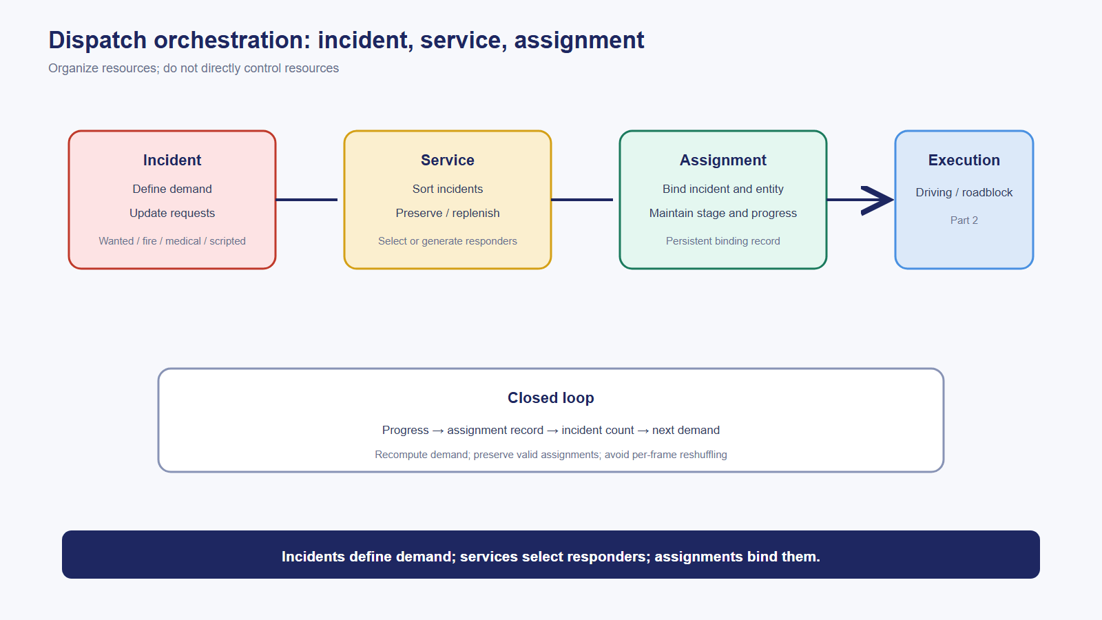
This chapter does not describe how one police vehicle drives or how a roadblock becomes physical geometry. It describes the orchestration chain: an incident creates demand, a service selects or creates responders, and an assignment binds the responder to the incident. Dispatch organizes resources; it does not directly control them.
4.1 Original mechanism
The dispatch runtime is a six-layer ownership chain. The central three layers are incident, service, and assignment.
Incident layer. The incident manager is a replicated registry of active incidents. It owns a bounded incident array, mirrors local and remote records, and removes incidents when they end. It is not the response-decision core. It does not decide police behavior, generate responders, or create assignments.
The bounded registry is also a resource budget. Active incidents are limited because each incident can create demand for police, fire, or medical resources. The limit prevents incident production from becoming an unbounded responder-production mechanism.
The registry uses a replicated pointer-slot pattern: a fixed-size network slot can reconstruct a polymorphic incident object from its serialized type. When the type changes, the wrapper destroys and rebuilds the correct derived object. Admission is also a feasibility gate: duplicate incidents, invalid network ownership, unavailable services, and unreachable fire locations can be rejected before entering the active registry.
Incident subclasses define demand policy:
- A wanted incident converts the current wanted level into resource demand through a data-side response table. Nearby incidents may reshape or merge demand rather than doubling it.
- An arrest incident is a narrow request for a small police response.
- A fire incident owns a cluster, center, radius, timed persistence window, vehicle wreck references, and responder bookkeeping. It requests only fire services and closes only after the fire and its active response state have both settled.
- A scripted incident receives externally configured demand and waits for the required service types to arrive.
- An injured-person incident requests medical response and may reject service when the local combat state makes arrival unsafe.
Demand is not frozen at creation. The incident updates first, then recomputes its current request. This ensures that service demand reflects the latest search area, wanted level, fire state, or injury state.
Service layer. The service is the bridge between incidents and assignments. Its stable cycle is: build and sort pending incidents, let incidents update requests, preserve valid existing assignments, acquire or generate resources, and create assignments for the remaining demand. The preserve-existing step prevents a responder already in pursuit from being revoked and reassigned every frame.
Assignment layer. The assignment registry stores active replicated assignments, while each assignment is a thin persistent binding between an incident, an entity, and a dispatch type. It records timestamps, arrival state, completion state, and progress. An assignment is not the execution task itself. It is the durable handoff between dispatch orchestration and the downstream task system.
Assignments write progress back to incidents. Incident completion is therefore determined by the counts and state maintained through the assignment layer: incident defines demand, service selects resources, assignment records execution progress.
Summary: dispatch is an incident → service → assignment decision chain. Incidents define demand, services select or generate responders, and assignments maintain persistent bindings and progress.
4.2 UE5 migration choice
Dispatch is polymorphic, mutable, and cross-entity. Its active scale is small, while its relationships are strong. It should therefore remain an object-oriented runtime service, with UE5 replication used at the registry boundary rather than forcing the whole system into a homogeneous batch model.
The project-owned layers are the incident and assignment registries, incident demand policies, service reuse and generation, and assignment state transitions. The execution layer remains separate.
4.3 Prototype status and plan
Dispatch orchestration is not implemented. The prototype already provides a compatible identity foundation: handles and serials for registry entries. Existing admission gates, idempotent reservation, and source-matching rules provide migration precedents for incident admission, service reuse, and assignment ownership.
The dispatch layer should be built after the lower-level relationship and readiness rules are stable. The roadblock and responder execution side belongs to Part 2.
5. Traffic Readiness Gates: Vehicle Admission Conditions
Question for this chapter: the previous chapters assume that an eligible vehicle exists. Who decides whether a vehicle is currently allowed to enter traffic, and how does the decision report the first blocking condition?

This is the only chapter that can be compared directly with implemented prototype code. The gate is the admission contract between the vehicle runtime and the traffic runtime.
5.1 Original mechanism
The readiness snapshot exposes the atomic facts required for traffic participation: traffic enabled, valid vehicle handle, non-dummy LOD, driver present, command source present, lane metadata, and route metadata. These facts are composed into several views rather than collapsed into one boolean.
The shell gate evaluates runtime prerequisites: vehicle validity, LOD, driver, and command source. The metadata gate evaluates lane and route prerequisites. Metadata has no diagnostic meaning before runtime prerequisites are satisfied, so metadata checks are enabled only after the shell gate is open.
The local gate chain walks the ordered conditions and reports the first unsatisfied gate, including whether the blocker is before the shell, at the shell, or in metadata. This makes the result useful for diagnostics, tests, and operational inspection.
The diagnostic facade is layered. Lower snapshots provide accurate facts; higher snapshots aggregate readiness, problems, summaries, state rows, signatures, and inspection descriptors. The same fact is calculated once and consumed at different resolutions.
5.2 Why readiness must be a graded gate, not a bool
“Can this vehicle participate in traffic?” is not a yes/no fact. A vehicle can be blocked because it is invalid, a dummy, driverless, missing a command source, or missing lane and route metadata. A boolean collapses these causes and makes debugging expensive.
The readiness chain is pure query work: it changes no state, registers no per-frame update, and is built only when requested. The cost is additional types and functions; the benefit is a precise, testable contract across system boundaries. Each failed condition is also an acceptance metric for an upstream system: LOD must resolve dummy state, seat ownership must provide a driver, driving authority must provide a command source, and the road layer must provide lane and route metadata.
Summary: readiness is an ordered, queryable, testable contract. It is the point at which the vehicle runtime becomes admissible to the traffic runtime.
5.3 Prototype status and plan
This is the most complete traffic-related part of the prototype. BuildTrafficReadinessSnapshot and its shell, metadata, local-chain, state-row, summary, signature, and facade views are implemented and covered by focused tests. The traffic AI after the gate—road graph, junctions, signals, routing, driving policy, dispatch execution, and vehicle executors—has not been implemented.
6. Migration Decisions: The Traffic Part 1 Checklist
The implementation order follows the ownership graph:
- Build the streaming road graph and its semantic query surface.
- Build vehicle-to-junction membership and reconciliation.
- Add junction right-of-way and phase output.
- Add the signal facade and pure stop policy.
- Add incident, service, and assignment registries.
- Connect traffic admission to the readiness gate before allowing downstream takeover.
The prototype already has the strongest foundation at the entrance: the readiness gate is implemented, while the systems after admission are migration maps. This is a deliberate order. A downstream system can only be independently developed when its input contract is explicit.
Build admission first, then coordination
The readiness gate establishes what traffic ownership means: a valid, non-dummy vehicle with a driver, command source, lane metadata, and route metadata. Once that contract is stable, road, junction, signal, and dispatch systems can develop against a known input state.
The traffic-side reuse boundary is also clear:
- Reuse engine facilities for streaming, local navigation, and signal presentation where appropriate.
- Build project-owned road semantics, junction arbitration, stop policy, and dispatch relationships.
- Keep replication at explicit registries and relationship boundaries.
- Keep execution and physical integration in the lower vehicle/runtime layer.
The central migration rules are replicate deterministic inputs when outputs can be derived, and reject infeasible requests at admission. The first keeps signal phases consistent across clients; the second keeps invalid vehicles and impossible dispatch requests out of active runtime state.
AI Collaboration Review
AI’s value in this article was specification work rather than autonomous design. It helped align multiple source notes into a consistent ownership map and identify negative boundaries: the signal facade does not own phase scheduling; the incident registry is not the response policy; the assignment is not the execution task; and the road wrapper is not the road-data owner.
On the prototype side, the review focused on BuildTrafficReadinessSnapshot, its shell and metadata gating, and the diagnostic views around the readiness chain. The result is an explicit separation between implemented code and migration planning. AI helps establish the specification; the engineer decides the specification.
*This is an article in the “How to Build an Open-World Game” series. Part 1 covers traffic scheduling and decisions: road networks, junction right of way, traffic signals, dispatch orchestration, and readiness gates. Part 2 covers execution. The prototype currently implements the readiness gate and its diagnostic views; the traffic AI after admission remains a migration map. Project names and source identifiers are anonymized for publication.*